6881076C25-E September 5, 2008
Theory of Operation: ASTRO Spectra VOCON Board 3-29
During this process, the MCU does power diagnostics. These diagnostics include verifying the MCU
system RAM, and verifying the data stored in the internal EEPROM, external EEPROM, and FLASH
ROMs. The MCU queries the DSP for proper status and the results of DSP self tests. The DSP self
tests include testing the system RAM, verifying the program code in ROM U404, and returning the
ADSIC configuration register checksum. Any failures cause the appropriate error codes to be sent to
the display. If everything is OK, the appropriate radio state is configured and the unit waits for user
input.
On power-down, the user opens the radio on/off switch, removing the B+_SENSE signal from the
controller board. This does not immediately remove power, as the MCU holds this line active through
B+_CNTL. The MCU then saves pertinent radio status data to the external EEPROM. Once this is
done, B+_CNTL is released, shutting off SW_B+ at Q106 and shutting down the 5-Vdc regulator
U709. When the regulator slumps to about 4.7 Vdc, supervisory IC U726 activates a system reset to
the SLIC, which in turn resets the MCU.
3.3.14 VOCON Board Signals
Due to the nature of the schematic-generating program, signal names must be different when they
are not directly connected to the same point. The following tables provide a cross-reference to the
various pinouts for the same functional signal.
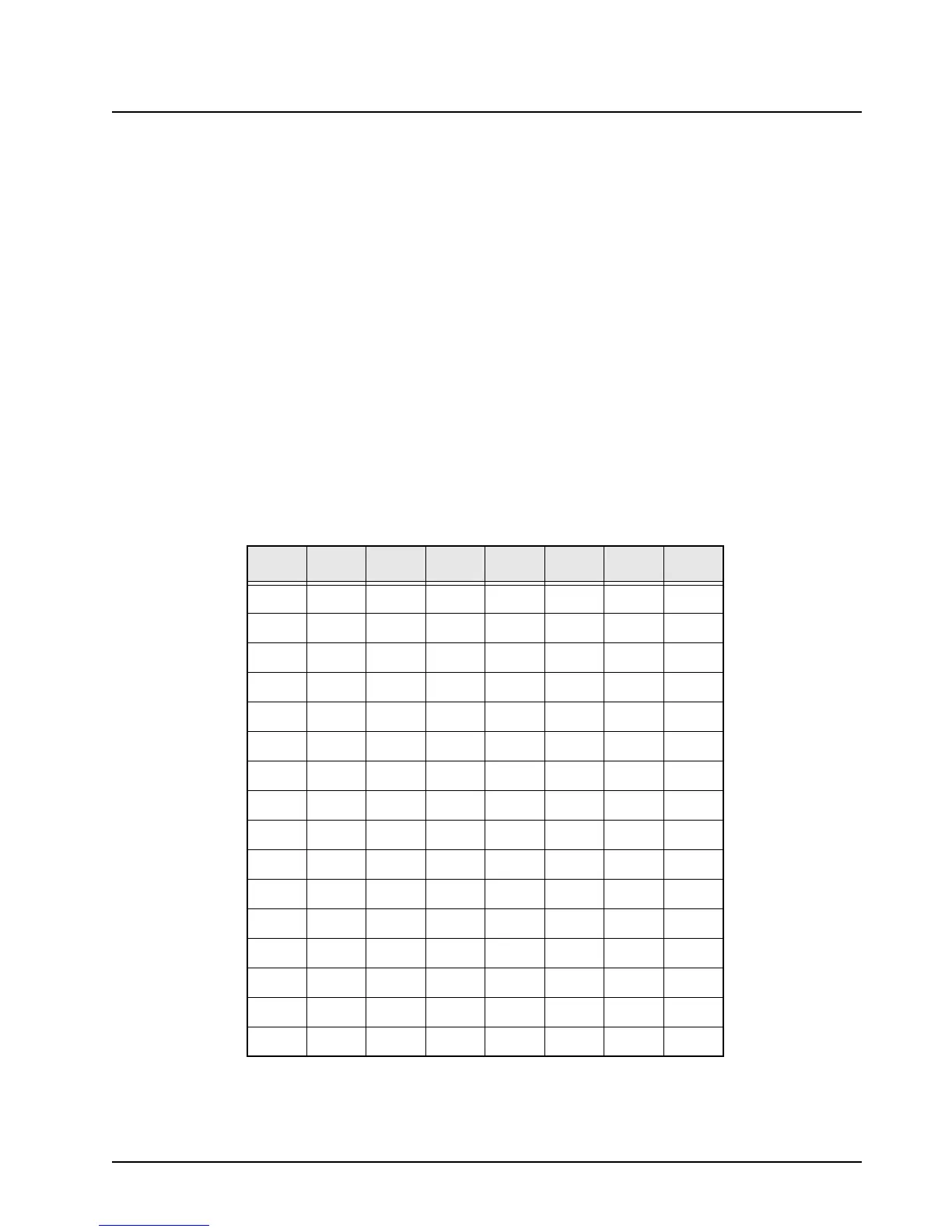
Table 3-2. VOCON Board Address Bus (A) Pinouts
Bus U402 U403 U404 U405 U406 U414 U415
A0 A4 A4 20 C2 E9 A4 –
A1 B4 B4 19 D3 E10 B4 –
A2 A3 A3 18 D2 E8 A3 –
A3 B3 B3 17 E2 – B3 –
A4 A2 A2 16 D4 – A2 –
A5 B2 B2 15 B1 – B2 –
A6 J6 J6 14 E3 – J6 –
A7 K7 K7 13 F1 – K7 –
A8 J7 J7 3 F2 – J7 –
A9 K8 K8 2 F3 – K8 –
A10 B8 B8 31 G1 – B8 –
A11A8A81 J2 – A8–
A12B7B712K1– B7–
A13 J3 – 4 H3 D9 – 2
A14 – – 5 G2 B9 – 1
A15 K3 K3 11 H2 D10 J3 –
 Loading...


