September 5, 2008 6881076C25-E
3-68 Theory of Operation: Power Amplifiers
3.7.2 UHF Band Power Amplifiers
3.7.2.1 High-Power Amplifier
3.7.2.1.1 Transmitter
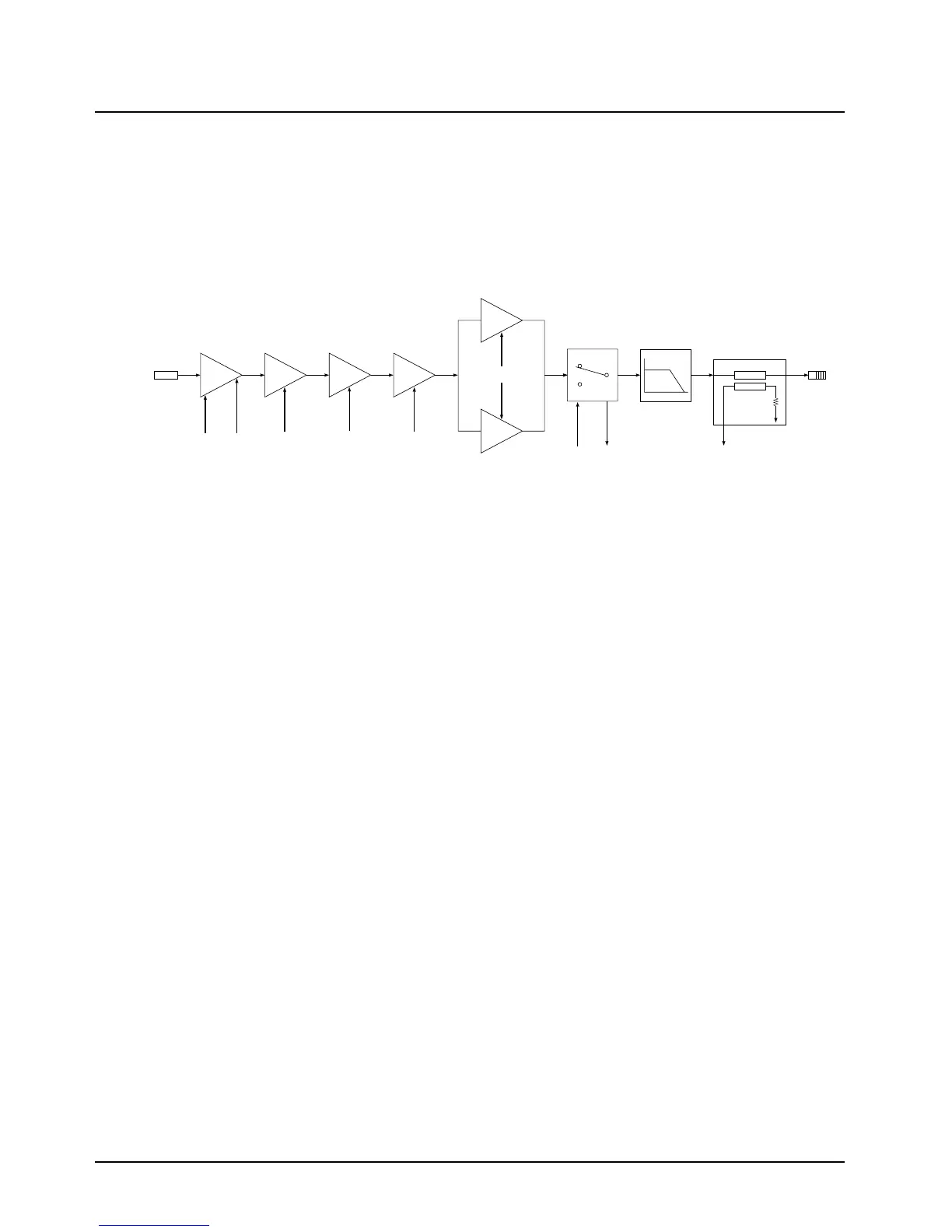
The high-power Spectra amplifier is discussed in the following text. A block diagram of the circuit is
shown in Figure 3-24.
Figure 3-24. UHF High-Power, Power Amplifier Block Diagram
Transmit Low Level Amplifier (LLA)
The LLA is the first stage of the PA and provides a gain that is a function of a control voltage. This
control voltage comes from the Regulator Power Control IC (RPCIC) on the command board. The
magnitude of the control voltage depends on PA output power, temperature, and final amplifier
current drain.
The LLA, Q5801, is unique in that its gain is controlled by varying the collectors current rather than
its voltage. Q5801 and associated circuitry (Q5806, Q5800, R5805, and R5818) are best described
as a voltage-controlled current source. This means that the collector current of Q5801 is controlled
by the magnitude of the control voltage.
Second Amplifier Stage
The second stage of the PA, Q5803, amplifies the output of the LLA to a level sufficient to drive the
third stage device, Q5850. Q5803 amplifies the LLA output from approximately 250 mW to
2.5 Watts.
Third Amplifier Stage
The third stage uses a 2.5-Watt input to 16-Watt output device. It is driven by the second stage
through a matching circuit that consists of C5851, C5852 C5850, C5858, and L5850. L5851 and
L5852 give the device a zero-Vdc base bias (required for Class-C operation). The network of L5853,
L5854, C5856, C5857, and R5850 provide A+ to the collector.
Driver Stage
The driver stage uses a 15-Watt input to 50-Watt output device. It is driven by the third stage through
the matching network consisting of C5853, C5854, C5855, C5861, C5862, and associated
transmission lines. The DC bias path for the base is provided by L5855 and L5857. C5859, R5851,
and C5860 are for the purpose of suppressing parasitic oscillations. Note that the capacitors C5861,
C5862, C5863, and C5864 are placed on the bottom side of the PC board.
FINAL AMPLIFIER
Q5875
25C29
Q5876
25C29
Q5851
25C30
Q5850
25C27
Q5803
25C09
Q5801
82D50
LLA 2ND STAGE 3RD STAGE DRIVER
250mW 2W 15W 50W
30mW
J5901
INJECTION
CONTROL
VOLTAGE
K9.4
9.6V
FILTERED
A+
FILTERED
A+
FILTERED
A+
PIN
ANTENNA
SWITCH
HARMONIC
FILTER
DIRECTIONAL
COUPLER AND
DETECTOR
K9.4
TO
RECEIVER
E5802
FORWARD
POWER
DETECT
J3853
ANTENNA
CONNECTOR
MINI UHF
110W
125W
MAEPF-22045-O
 Loading...


