September 5, 2008 6881076C25-E
4-48 Troubleshooting Procedures: Power Amplifier Procedures
Begin troubleshooting by connecting an RF power meter and appropriate power load to the antenna
connector. Connect the control cable and the power cable. Make sure the ignition sense lead is also
connected to the positive lead of the power supply. Note that a regulated DC power supply capable
of at least 30 A. is necessary to power a high-power Spectra transmitter. Remove the radio bottom
cover. Remove the PA shield by pulling straight up on the plastic handle. This must be done
carefully, as the edge of the PA shield can damage components on the PA board if it is removed
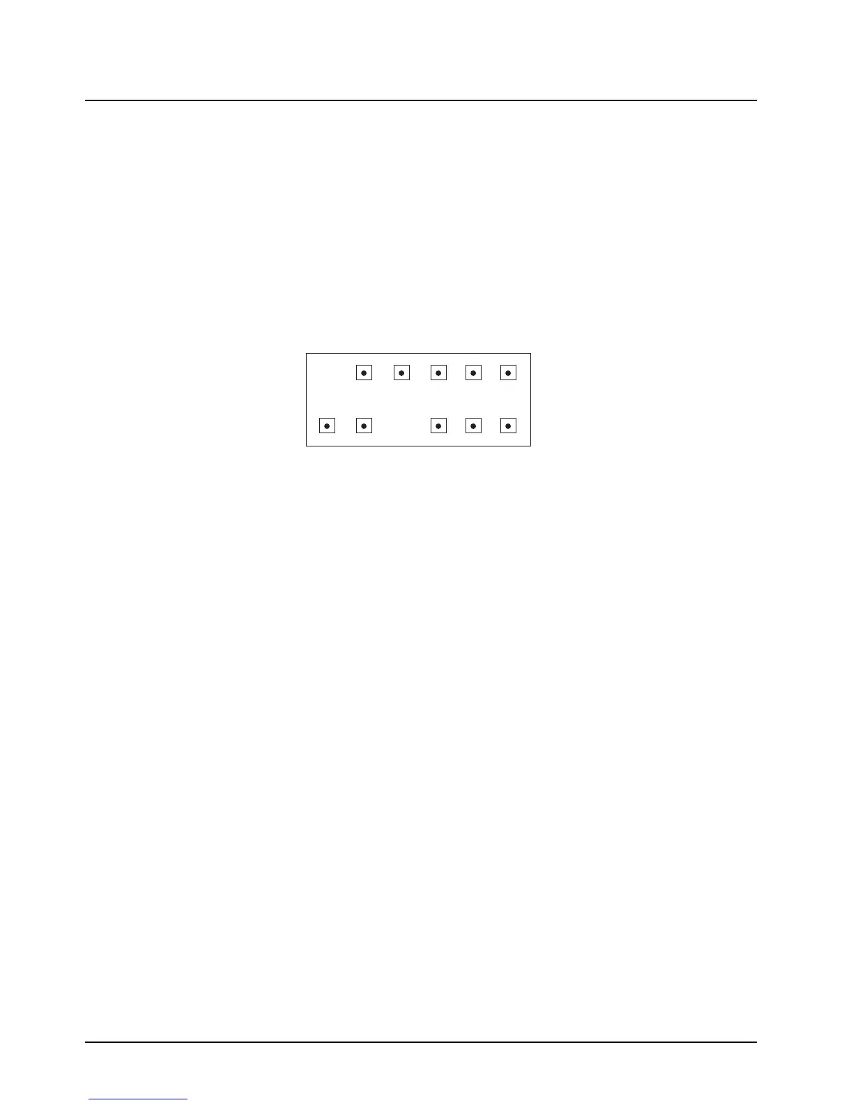
unevenly. Set the power supply to 13.4 V. The radio may now be turned on. All critical voltages may
be measured at connector J1 from the top side of the PA board. A diagram of the connector pin-out
as viewed from the top side of the PA board is shown in Figure 4-7.
Figure 4-7. Connector Pin-Out – High-Power Amplifier
12 10 8 6 4 2
11 9 7 5 3 1
Pin Configuration of J1
As Viewed From Top of PA Board
1 Control Voltage Limit
2 Control Voltage Drive
3 Current Sense +
4 Key 9.4V
5 Filtered A+
6 Temp-Sense
7 Not Connected
8 Forward Power Detect
9 9.6V
10 Current Sense –
11 Not Connected
12 10 8 6 4 2
11 9 7 5 3 1
Pin Configuration of J1
As Viewed From Top of PA Board
1 Control Voltage Limit
2 Control Voltage Drive
3 Current Sense +
4 Key 9.4V
5 Filtered A+
6 Temp-Sense
7 Not Connected
8 Forward Power Detect
9 9.6V
10 Current Sense –
11 Not Connected
12 Not Connected
 Loading...


