6881076C25-E September 5, 2008
Troubleshooting Procedures: ASTRO Spectra Procedures 4-3
In the case of multiple errors, the codes are logically OR’d and the results displayed. As an example,
in the case of an ADSIC checksum failure and a DSP ROM checksum failure, the resultant code
would be 02/A1. Following is a series of troubleshooting flowcharts which relate to each of these
failure codes.
4.1.3.1 Power-Up Sequence
Upon RESET* going active, the MCU begins to execute code which is pointed to by the vector stored
at $FFFE, $FFFF in the FLASH ROM. The execution of this code is as follows:
1. Initialize the MCU (U204).
2. The control head’s MCU turns on the:
- Green LED for the W3 model.
- TX and Busy LEDs for the W4, W5, W7 and W9 models.
3. Initialize the SLIC (U206).
4. CONFIG register check. If the CONFIG register is not correct, the MCU will repair it and loop.
5. Start ADSIC/DSP:
- Bring the ADSIC reset line high.
- Wait 2ms.
- Bring the DSP reset line high.
6. Start EMC:
- Set the EMC wake-up line low (emc irq line).
- Wait 5ms.
- Set the EMC wake-up line high.
- Wait 10ms.
- Set the EMC wake-up line low (emc irq line).
- Wait 5ms.
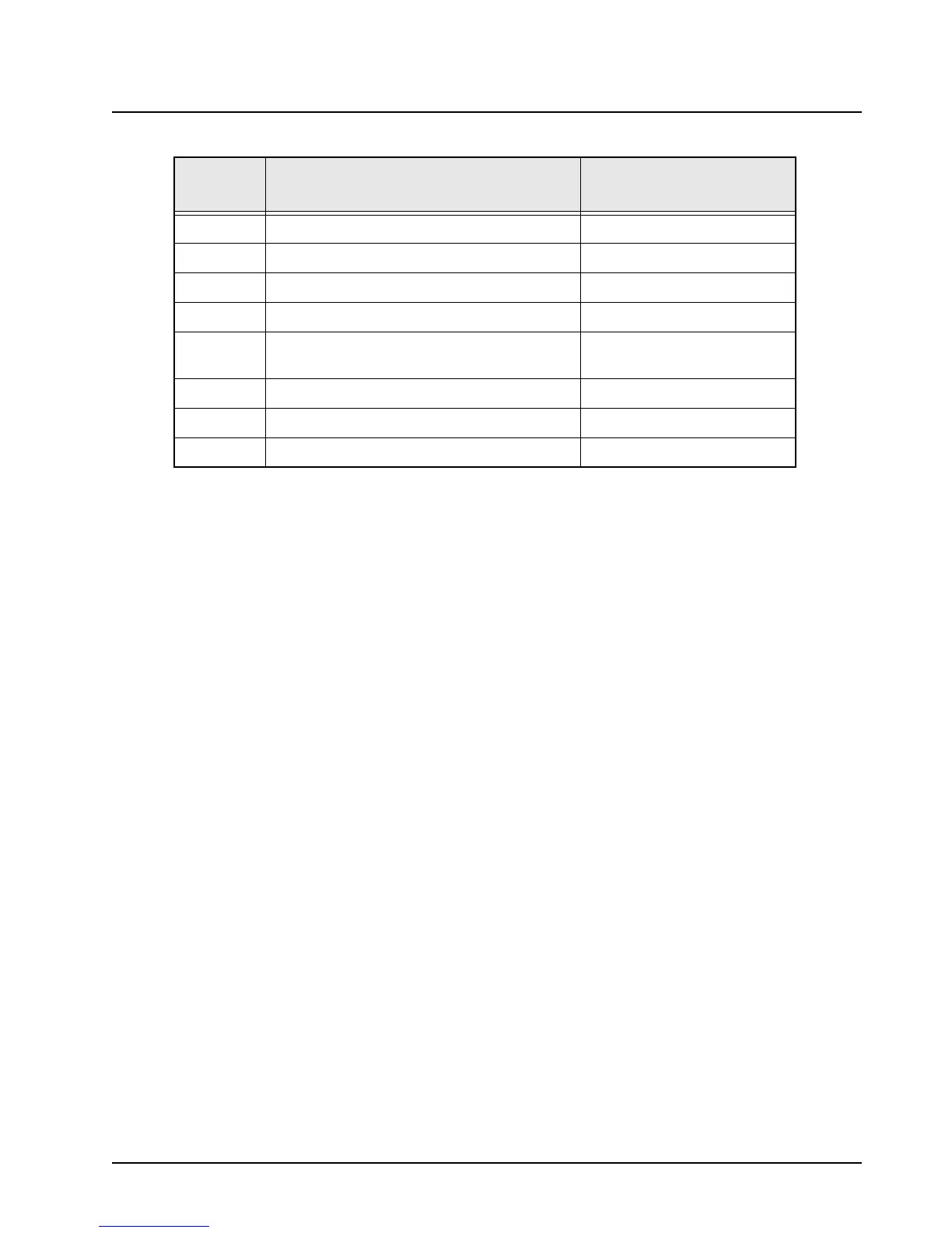
02/81 DSP ROM checksum failure Chart C.12 (p. 5-10)
02/82 DSP RAM 1 failure Chart C.15 (p. 5-12)
02/84 DSP RAM 2 failure Chart C.14 (p. 5-11)
02/88 DSP RAM failure - Note: Not a checksum failure Chart C.13 (p. 5-11)
02/90 General DSP hardware failure (DSP start-up
message not received correctly)
Chart C.16 (p. 5-12)
02/A0 ADSIC checksum failure Chart C.11 (p. 5-10)
09/10 Secure option not communicating with radio Chart C.17 (p. 5-13)
09/90 Secure hardware failure Chart C.18 (p. 5-13)
Table 4-1. Power-Up Self-Check Error Codes (Continued)
Error
Code
Description Troubleshooting Chart

 Loading...


