September 5, 2008 6881076C25-E
4-26 Troubleshooting Procedures: Power Amplifier Procedures
Testing Low-Level Amplifier (LLA) Circuitry
Proper operation of the LLA can be checked by monitoring the voltage across resistor R3804. The
voltage should measure in the range of 0.4 V to 1.0 V, depending on the value of control voltage. A
0.4-V reading corresponds to a low control voltage (4 to 5 V) and a 1.0-V reading corresponds to a
high control voltage (up to control voltage limit).
Measure LLA voltages according to Table 4-9. If the DC bias conditions are correct, check to see if
the LLA is providing drive power to Q3804. Do so by checking Q3804's collector current under
normal drive conditions, as follows:
• Remove L3806 (be sure to reinstall after testing).
• Solder wires to the remaining pads. Place an ammeter in series with Q3804 collector.
• Check for 0.2 to 0.5 A. (depending on control voltage).
NOTE: With no RF drive to the input of the PA, Q3804 collector current should be zero.
NOTE: The LLA voltages change with different control voltages. An example of LLA voltages with
control voltage equal to 8.0 V and 6 V is shown.
If Q3804 draws no current under normal conditions, then check for short or open input cable, or for
defective parts in the matching circuitry between Q3801 and Q3804.
Testing Second Stage Circuitry Q3804
The second stage is a typical Class-C stage, except the base is biased with resistors R3809 and
R3810. The necessary conditions for proper operation of this stage are input drive power, and bias
conditions as shown in Table 4-9.
NOTE: If it is necessary to replace Q3804, use a hot-air blower to remove and replace the part. It is
important that the replacement device's case be properly soldered to its heatsink. Do so by
flowing a small bead of solder around the rim of the device while it is clamped in the hot-air
soldering device. The base and collector leads must be hand-soldered on the bottom side of
the board.
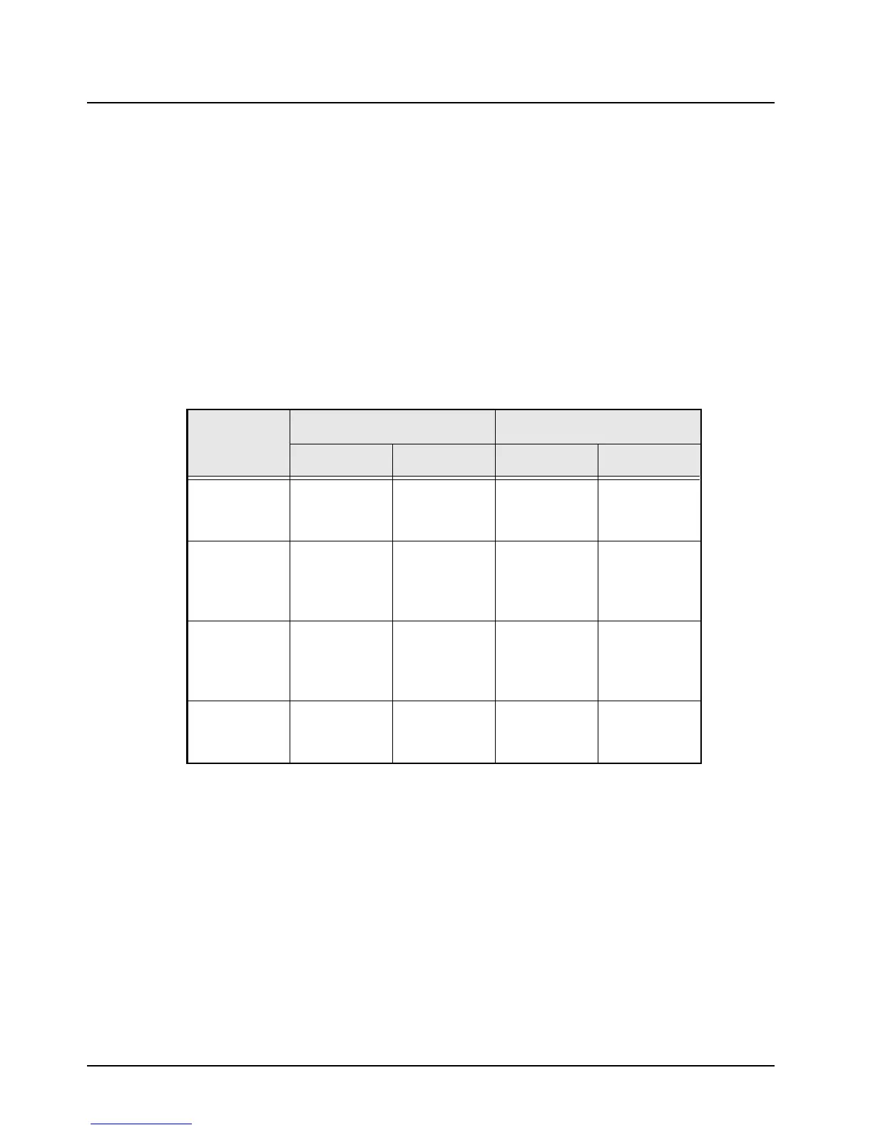
Table 4-9. LLA and 2nd Stage Typical Voltages
CONTROL
VOLTAGE
RF DRIVE OFF RF DRIVE ON
8.0 V 6.0 V 8.0 V 6.0 V
Q3801
Base
Collector
–
0.7
8.3
–
0.7
9.0
–
0.7
8.0
–
0.5
8.8
Q3802
Base
Collector
Emitter
–
7.7
2.0
8.3
–
8.4
1.4
9.0
–
7.5
2.3
8.0
–
8.2
1.2
8.8
Q3806
Base
Collector
Emitter
–
5.1
7.7
4.5
–
4.1
8.4
3.4
–
5.1
7.5
4.5
–
4.1
8.2
3.4
Q3804
Base
Collector
–
0.5
9.6
–
0.5
9.6
–
0.0
9.5
–
0.2
9.5
 Loading...


