6881076C25-E September 5, 2008
Theory of Operation: ASTRO Spectra Plus VOCON Board 3-45
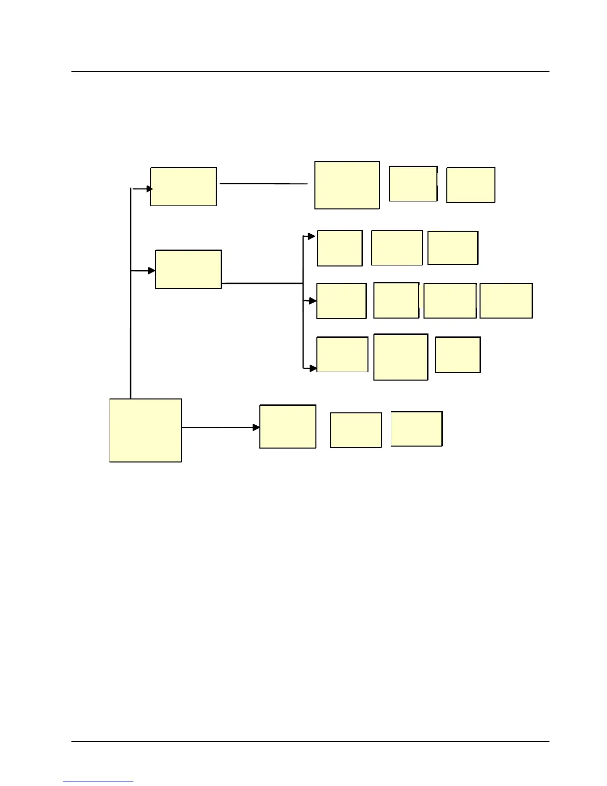
3.4.9 ASTRO Spectra Plus Voltage Regulators
The ASTRO Spectra Plus VOCON board contains two voltage regulators, a 3-V regulator (U411)
and a 1.8-V regulator (U410). SW+5-V, which is routed to the ASTRO Spectra Plus VOCON board
from the command board, drives the two regulators. Figure 3-19 shows the DC distribution for the
ASTRO Spectra Plus VOCON board.
Figure 3-19. ASTRO Spectra Plus VOCON DC Distribution
U410 and U411 are on Semiconductor LP2951CD adjustable regulators. The output voltage of these
regulators is determined by the resistive divider network between the regulator output and the error
amplifier feedback input. The LP2951 has error output lines which are open collector and requires a
pull up resistor (R332). The error line is high when the output voltage is high and low otherwise.
U412 is a 4.2-V detect circuit for the SW_5-V line. The output of this detector is tied to the error
outputs of the LP2951 regulators as a low voltage detect (LV_detect ) circuit. C438 provides delay on
the LV_detect line during startup. This is to allow all regulators to settle prior to Patriot U300 coming
out of reset.
V = 3.0 V
V = 1.8V
PATRIOT
Core, EIM
2M x 16
FLASH
256 x 16
SRAM
EEPOTs
MAX5160
USB
PATRIOT
Buses
SSI,SPI,UART
MC145483
CODEC
Audio/
Modulation
OP amps
Clock Gen
buffers
16.8 MHz
Ref Osc
KRSIC
ADDAG
Voltage
Conversion
block
Secure
SSI to SPI
conversion
circuitry
USB/RS232
quad mux
Voltage
Conversion
block
SW_5V
(from RPCIC
on command
board)
5V
5V
ON
Semiconductor
LP2951
ON
Semiconductor
LP2951
 Loading...


