6881076C25-E September 5, 2008
Theory of Operation: Power Amplifiers 3-65
3.7.1.3.3 Power Control Circuitry
Command Board Circuitry
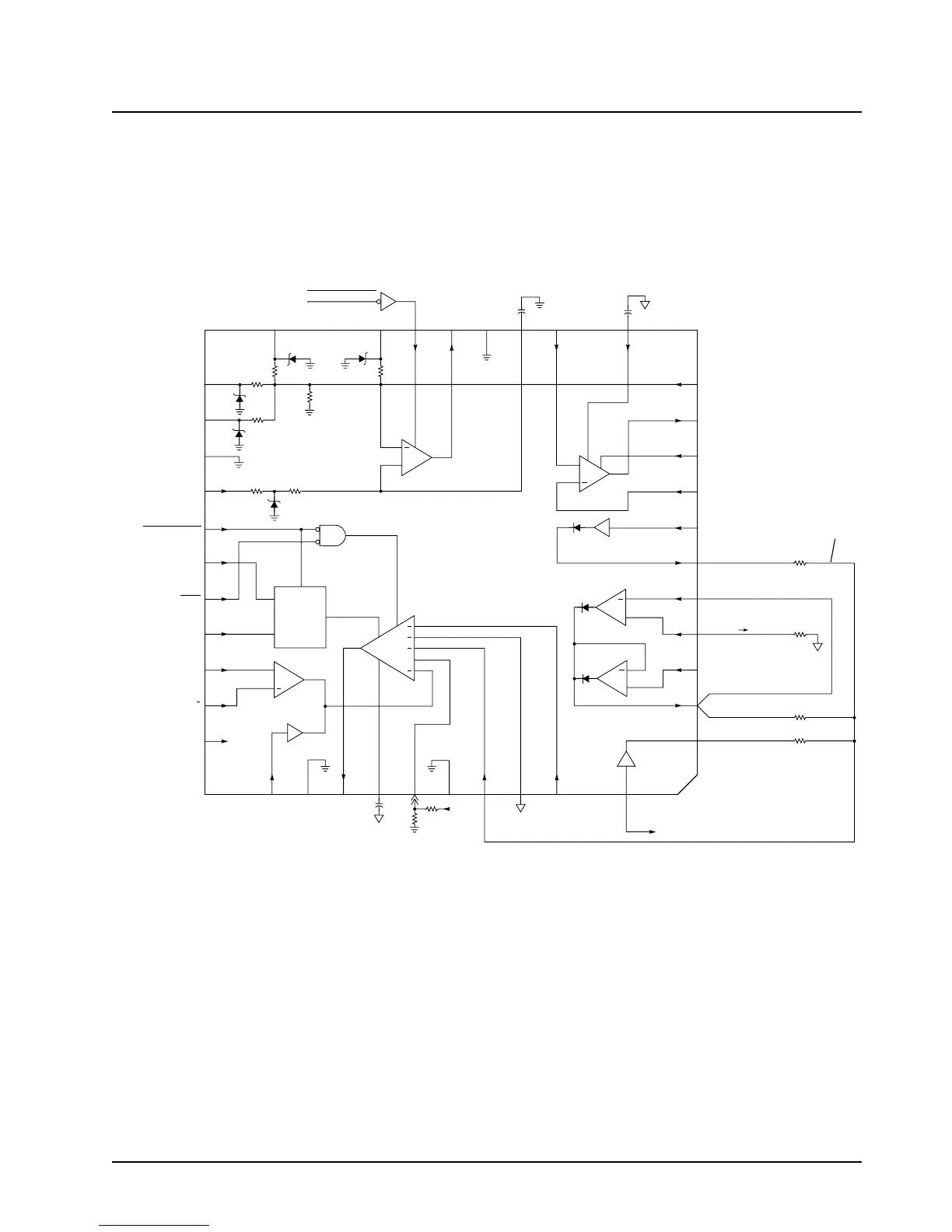
Inside U500, the Regulator Power Control IC (Figure 3-23), is an operational amplifier that has four
inverting inputs, and non-inverting input at pin 44 which is the reference input for the entire power
control loop of the power amplifier. The 3.2-V reference voltage at U500-44 is produced by dividing
SW +5-V with the voltage-divider circuit, R514 and R515.
Figure 3-23. Regulator/Power Control IC Block Diagram
The power control loop is controlled by the microprocessor U204 on the VOCON board. Through the
SLIC IC U206, the microprocessor enables the RPCIC by pulling TX PA ENABLE (U500 pin 33) low
while the radio synthesizer is locked (U500 pin 35). U520 writes data to a digital-to-analog converter,
U502, to change and control the power-set voltage from pin 10 of U502 to pin 6 of U500. The voltage
on this line, 1.5 to 5 V, will be inversely proportional to the power out of the PA, with 5 V producing
the lowest power output. This voltage may be set with RSS (Radio Service Software) or CPS
(Customer Programming Software).
N.C.
A+
TX P.A. ENABLE
LOCK
CURRENT SENSE +
FROM R9875
CURRENT SENSE
FROM R9875
KEYED 9.4V INPUT
9.6V DRIVE
UNSW 5V REF
9.6V SENSE INPUT
5V DRIVE TO Q502
5V CURRENT SENSE
5V FEEDBACK
TEMPERATURE SENSE
INPUT
TEMPERATURE SENSE
OUTPUT TO 500-2
POWER SET FROM
U502 1.5V 5 VOLTS
FORWARD DET.
VOLTAGE
POWER SET OUT TO
PIN 2 VIA R507
TX CURRENT
LIMIT FROM
U502-15
CONT.
AMP
OUT
REF.
3.2V
5V
CONT.
AMP IN
VOLTAGE
CONTROL
LIMIT
POWER
SET
N.C.
N.C.
N.C.
N.C.
N.C.
N.C.
REGULATOR
GROUND
13.8V
9.6 VOLT
REGULATOR
PA ENABLE
ONE-
SHOT
WIDE-BAND
ENABLE
CONTROL AMP
CURRENT SENSE
AMP
CURRENT
LIMIT SET
BUFFER
POWER CONTROL
GROUND
PACKAGE FLAG
GROUND
POWER SET
BUFFER
DIRECTIONAL
COUPLER BUFFER
THERMISTER
BUFFER
5V REGULATOR
PACKAGE
GROUND
U500
29
30
31
32
33
34
35
36
37
38
39
28
27 26 25 24 23 22 21 20
19
18
17
16
15
14
13
12
11
10
9
8
7
6432144434240 41 5
+
+
+
Q
+
+
+
+
+
Q538
RPCIC ENABLE
FORWARD BUFFERED
OUT
TO PIN 10
U502 DAIC
R516
100K
R509
68K
R507
47K
R508
68K
RESISTIVE
SUMMING
NETWORK
REGULATOR/POWER CONTROL IC U500
MAEPF-22034-O
 Loading...


