6881076C25-E September 5, 2008
General Overview: Radio Power 2-9
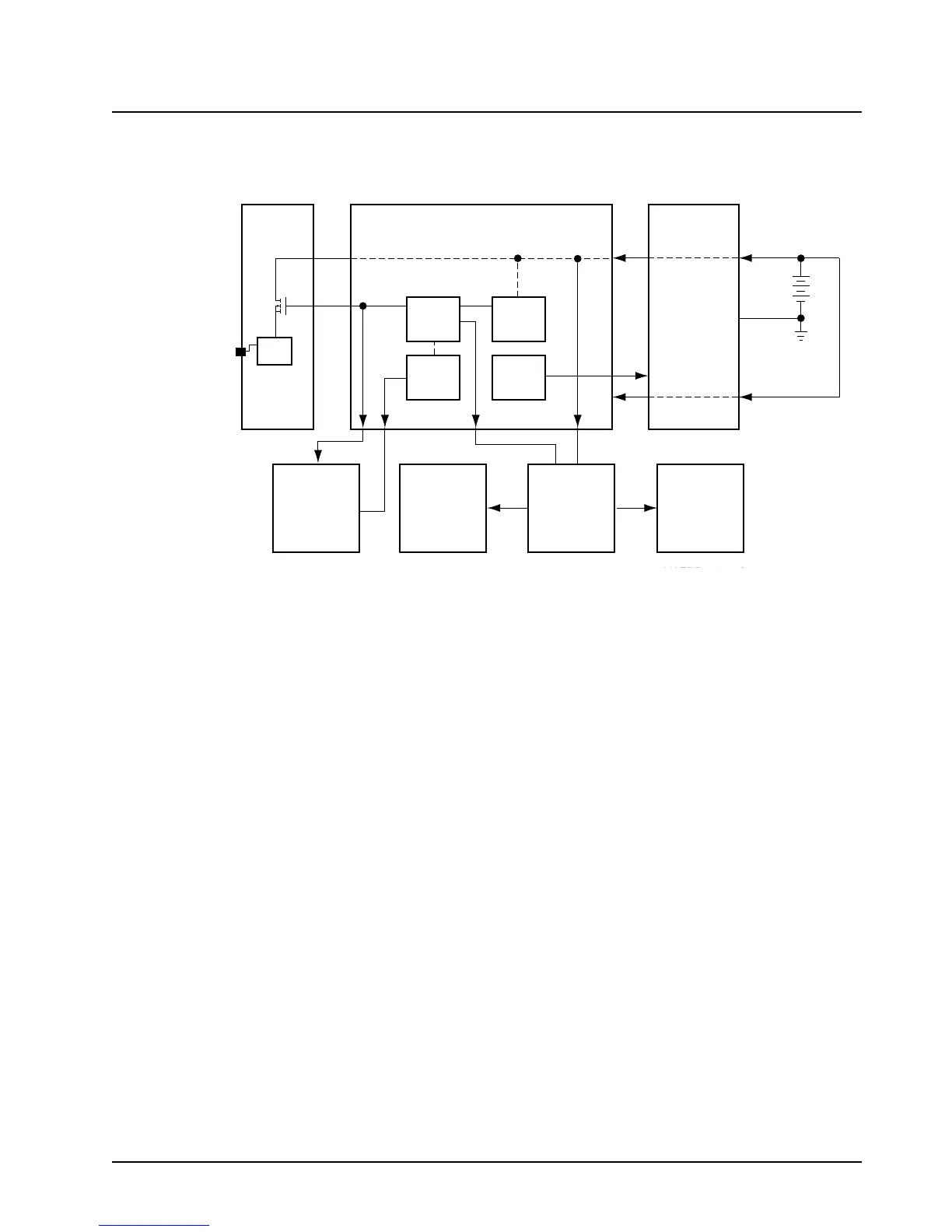
When the command board regulators are “on,” the 9.6-V output sources the command board and RF
board circuits. The switched +5 V is routed to the VOCON board. See Figure 2-1.
Figure 2-1. DC Voltage Routing Block Diagram
The 9.6 V and the A+ voltage are the main DC power for the RF board. Outputs from the RF board
provide DC power to the synthesizer and the receiver front-end filter. The RF board has an internal
+5-Vdc regulator that is sourced from the A+ voltage.
The voltage to power the 9.4-V regulator is produced by the command board’s 9.6-V regulator. The
9.4 V (referred to as “keyed 9.4 V”) is controlled by the VOCON board through P501, pin 45. This DC
voltage enables the transmitter’s RF power amplifier when the VOCON board senses a lock detect
from the synthesizer.
2.11.2 B+ Routing for ASTRO Spectra VOCON Board
Refer to Section 3.4, "ASTRO Spectra Plus VOCON Board," on page 3-38 for information on the
ASTRO Spectra Plus.
See Figure 2-2 on page 2-10 and your specific schematic diagram.
The A+ power for the radio is derived from the 12-V battery, which is applied to the command board
through connector P503, pins 5 and 9. This A+ voltage is routed through the command board to the
control head connector, P502, pin 30 and to the VOCON board, J501, pin 38.
The interconnect board couples the A+ voltage from the command board to the control head, where
a power FET (Q51) provides the means of controlling the main power source (SWB+) by the on/off
switch. SWB+ is routed back to the SIO/IC (U522) on the command board through connector P502.
The SIO/ICcontrols the RPCIC enable line.
When the RPCIC enable line toggles low, the 9.6-V and the SW+5-V regulators turn on.
The SW+5-V regulator is the main power source for the VOCON board. Digital and analog +5 V are
derived by filtering SW+5 V through .005 μH chokes L511 and L510 on the command board. These
two 5-V regulated supplies are used to partition the digital logic circuitry from the analog circuitry.
Control
Head
RF
Power Amp
Command Board
n/Off
5W
A+
A+
IGN
J2-5
Keyed
9.4V
A+9.6V
9.6V
Battery
12V
P1
SWB+
9.6V
UNSW
+5V
SW
+5V
SW
9.4V
VOCON
Board
Synth
RF
Board
RF
Filter
9.6V
 Loading...


