September 5, 2008 6881076C25-E
4-34 Troubleshooting Procedures: Power Amplifier Procedures
4.5.1.2.3 Localizing Problems
Failure locations often can be determined by externally measured symptoms. Basic symptoms are
noted below with probable failure locations.
1. Low Power and High Current
- Check for improper load conditions caused by high VSWR external to the radio.
- Check output coax and mini-UHF connector.
- Check harmonic filter.
- Check output impedance-matching circuitry from the final device to the harmonic filter.
2. Low Power and Low Current
- If control voltage drive is equal to 9.2 V, then check per the above.
- If control voltage drive is less than 9.2 V, then check the control circuitry.
3. Power Intermittently Low (or Zero) and Current Less than 1 A. When Power Drops
- Check LLA stage.
4. Power Zero and Current Greater Than 3 A.
- Check harmonic filter, antenna switch, and matching circuits beyond final stage.
5. Power Zero and Current Between 1 and 3 A.
- Check driver and/or final stages.
6. Power Zero and Current Less Than 1 A.
- Check LLA/driver circuitry.
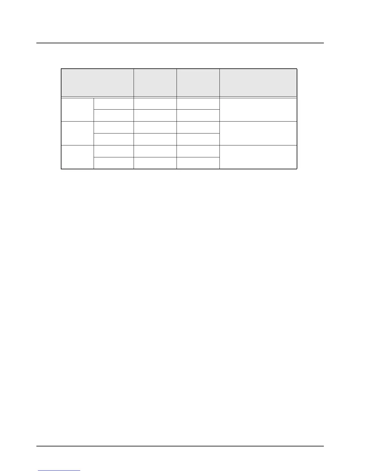
Table 4-12. Antenna Switch DC Voltage Chart
LOCATION TYPICAL RX
TYPICAL TX
NO PRE-
DRIVE
COMMENTS
CR3920
ANODE 0 1.6
CATHODE 0 0.8
CR3921
ANODE 0 0.8
CATHODE ––
CR3922
ANODE 0 <0.8
CATHODE ––
 Loading...


