6881076C25-E September 5, 2008
Troubleshooting Procedures: VCO Procedures 4-17
4.3.2.4 No or Low Modulation
Under standard test conditions with a 1 kHz tone injected and 4.5 kHz deviation, there should be 700
mV (RMS) ±20% present on P0601-10. If this level is not present, troubleshoot the modulation circuit
on the carrier board and then troubleshoot the audio circuitry. If the proper level is present,
troubleshoot the modulation circuitry on the VCO kit. If no failure exists, replace the VCO.
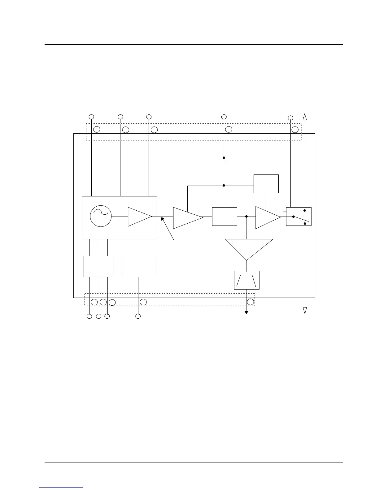
Figure 4-2. VCO Block Diagram – UHF Band
OSC
BUFFER
1
2
3
4
5
6
9
10
11
12
GPW-5861-A
P0601
-8V
AUX1
AUX2
MODULATION
SYNTHESIZER
FEEDBACK
RX
INJECTION
(12 dBm TYPICAL)
* MEASURED WITH VCO OUTPUT
TERMINATED INTO 50 OHMS.
AUX1, AUX2 HIGH 8V
AUX1, AUX2 LOW 1V
>
_
<
_
PINSHIFT
CIRCUITRY
MODULATION
CIRCUITRY
1ST
BUFFER
2ND
BUFFER
X2
DOUBLER
FEEDBACK
BUFFER
SYNTH
ACTIVE
BIAS
P0601
8 dBm Typical*
TX
INJECTION
(16 dBm TYPICAL)
K9.4
9.6
8.6
+SL
-SL
 Loading...


