6881076C25-E September 5, 2008
Troubleshooting Procedures: Power Amplifier Procedures 4-61
NOTE: For antenna switch transmit bias conditions, RF drive must be removed from PA.
4.5.2.2.3 Localizing Problems
Failure locations often can be determined by externally measured symptoms. Basic symptoms are
noted below with probable failure locations.
1. Low Power and High Current
- Check for improper load conditions caused by high VSWR external to the radio.
- Check output coax and mini-UHF connector.
- Check harmonic filter and J-straps for opens and/or shorts.
- Check output impedance-matching circuitry from the final device to the harmonic filter.
2. Low Power and Low Current
- If control voltage is equal to 10.0 V, then check per the above.
- If control voltage is less than 10.0 V, then check the control circuitry.
43 1.3 7.0
Loop Integrator Capacitor
44 2.1 3.2
Control AMP Reference
Q0500E 13.0 13.0
A+ - CR0500 Drop
Q0501C 12.3 12.3
VQ0500E - B/E Drop
Q0501E 0.2 0.2
V pin 23 - B/E Drop
Q0503E 0 1.5
V pin 42 - B/E Drop (TX)
Q0503C 13.6 9.0
Q0504B 13.6 12.9
A+ - B/E Drop (TX)
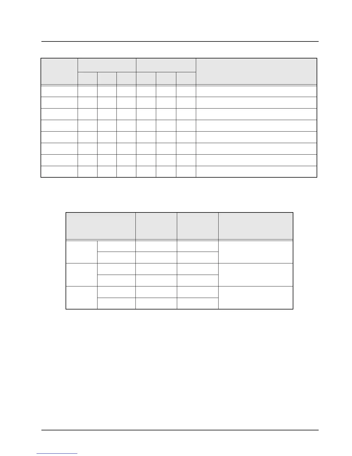
Table 4-21. Antenna Switch DC Voltage Chart
LOCATION TYPICAL RX
TYPICAL TX
NO PRE-
DRIVE
COMMENTS
CR5920
ANODE 0 1.6
CATHODE 0 0.8
CR5921
ANODE 0 0.8
CATHODE – –
CR5922
ANODE 0 <0.8
CATHODE – –
Table 4-20. Power Control DC Voltage Chart (Continued)
LOCATION
RX MODE TX MODE
COMMENTS
LOW TYP HI LOW TYP HI
 Loading...


