6881076C25-E September 5, 2008
Troubleshooting Procedures: Power Amplifier Procedures 4-71
4.5.3.1.3 Localizing Problems
Failure locations often can be determined by externally measured symptoms. Basic symptoms are
noted below with probable failure locations.
1. Low Power and High Current
- Check for improper load conditions caused by high VSWR external to the radio.
- Check output coax and mini-UHF connector.
- Check harmonic filter and J-straps.
- Check output impedance-matching circuitry from the final device to the harmonic filter.
2. Low Power and Low Current
- If control voltage is greater than 10 V, then check per the above.
- If control voltage is less than 10 V, then check the control circuitry.
3. Power Intermittently Low (or zero) and Current less than 1 A. when Power Drops
- Check Buffer Stage.
4. Power Zero and Current greater than 5 A.
- Check harmonic filter, antenna switch, and matching circuits beyond final stage.
5. Power Zero and Current between 2 and 5 A.
- Check Power Module.
6. Power Zero and Current less than 1 A.
- Check input coax.
- Check Buffer Stage.
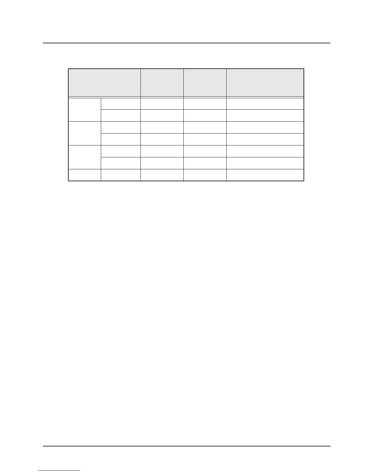
Table 4-25. Antenna Switch DC Voltage Chart
LOCATION TYPICAL RX
TYPICAL TX
NO PRE-
DRIVE
COMMENTS
CR9920
ANODE 0 1.6
TX Series P.I.N. diode
CATHODE 0 0.8
(on in TX mode)
CR9921
ANODE 0 0.8
TX Shunt P.I.N. diode
CATHODE – –
(on in TX mode)
CR9922
ANODE 5.15V <0.2
RX Series P.I.N. diode
CATHODE 4.45V 8.7
(off in TX mode)
Q9920
COLLEC 5.15V <0.2
 Loading...


