September 5, 2008 6881076C25-E
4-30 Troubleshooting Procedures: Power Amplifier Procedures
NOTE: Due to high operating frequencies, you must use specified Motorola parts when component
replacement is necessary. Substitute components may not work. It is also critical that you use
great care when replacing parts. Excessive solder or flux, longer than original leads on coax
connectors, misorientation of parts, and other commonly benign imperfections may cause the
radio's performance to degrade.
4.5.1.2.2 PA Functional Testing
To test the PA assembly for proper operation, perform the following steps:
1. Disassemble the PA assembly from the radio, leaving the power cable connected to the rear
connector. Replace the PA shield and cover. Disconnect the coax connectors and the ribbon
cable. Connect a power meter to the antenna port using minimum cable length.
a. When setting or measuring RF power, follow these guidelines to avoid measurement
errors due to cable losses or non 25/10-ohm connector VSVVR:
- All cables should be very short and have Teflon dielectric.
- Attenuators and 25/10-ohm loads should have at least 25 dB return loss.
- Mini UHF to 'N' adapter, P/N 58-80367B21, should be used at the antenna connector. All
other connectors should be 'N' type. No other adapters, barrel connectors, etc. should be
used.
b. Maximum input level to the PA is 20 mW. Too much input power could result in damage to
the LLA stage.
2. Apply the input power and DC voltages indicated in Table 4-10 to the power amplifier
assembly. To make the DC connections, use small spring-clips or make a test adapter similar
to that shown in Figure 4-5 on page 4-31.
3. Apply the required input power via an adapter cable. For this application, non 'N' type
connectors are acceptable.
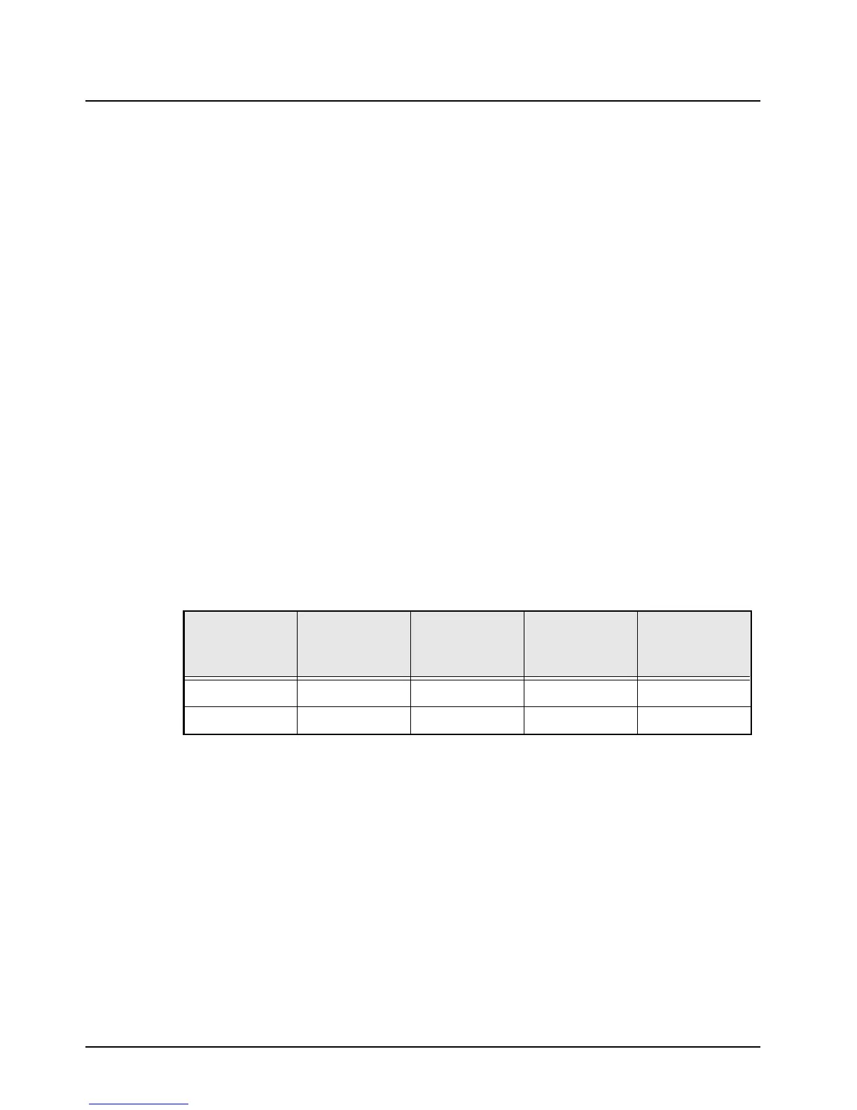
Table 4-10. DC Voltages and Input Power Chart
Test Keyed 9.4 V
CONTROL
VOLTAGE
DRIVE
POWER IN
(mW)
A+
(V)
Transmit 9.4 See note
a
a. Set initially to zero. Increase value until power equals 28 Watts or 9.2 V maximum.
Do NOT exceed 9.2 V.
10 13.4
Receive00013.4
 Loading...


