6881076C25-E September 5, 2008
Troubleshooting Procedures: Power Amplifier Procedures 4-25
If the command board and synthesizer are functioning properly, the PA must be defective. Details on
troubleshooting each circuit of the PA follow.
4.5.1.1.2 PA Functional Testing
NOTE: When setting or measuring RF power at VHF follow these guidelines to avoid measurement
errors due to cable losses or non-50-ohm connector VSWR:
- All coaxial cables should be low loss and as short as possible.
- Attenuators and 50-ohm loads should have at least 25 dB return loss.
- Mini UHF to 'N' adapter, P/N 58803671321, should be used at the antenna connector. All
other connectors should be 'N' type. No other adapters, barrel connectors, etc. should be
used.
Maximum input level to the PA is 20 mW. Too much input power could result in damage to
the LLA stage.
Methods of analyzing individual stages of the power amplifiers are detailed below. Most of the stages
are Class-C and must be analyzed under relatively high RF power levels. The following information
should help in isolation and repair of the majority of transmitter failures.
41 0 0 0 0 0 0
Ground
42 0 2.2 9.6
Control AMP Output (Approx 1/2-V Control)
43 1.3 7.0
Loop Integrator Capacitor
44 2.1 3.2
Control AMP Reference
Q0500E 13.0 13.0
A+ - CR0500 Drop
Q0501C 12.3 12.3
VQ0500E - B/E Drop
Q0501E 0.2 0.2
V pin 23 - B/E Drop
Q0503E 0 1.5
V pin 42 - B/E Drop (TX)
Q0503C 13.6 9.0
Q0504B 13.6 12.9
A+ - B/E Drop (TX)
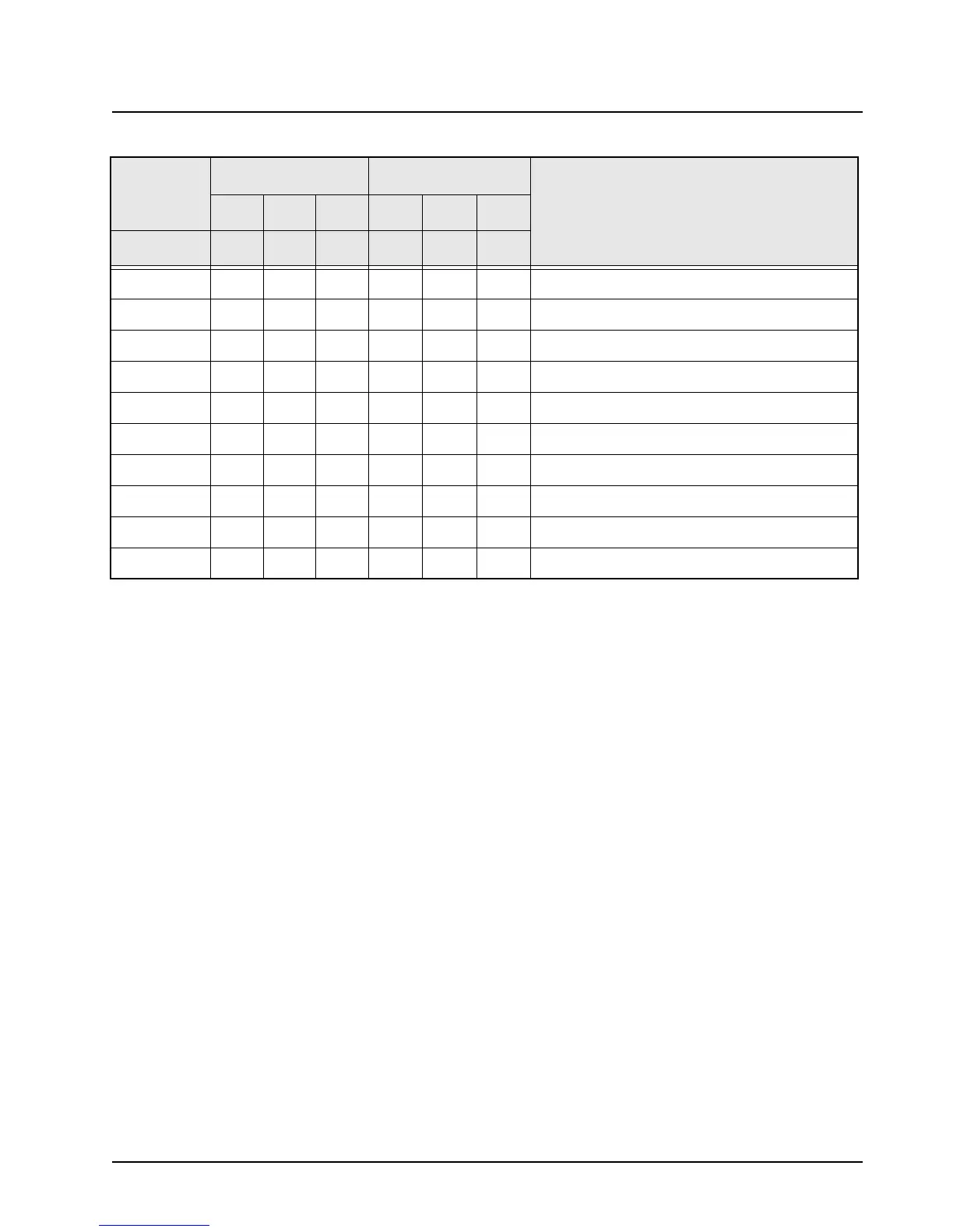
Table 4-8. Power Control DC Voltage Chart (Continued)
LOCATION
RX MODE TX MODE
COMMENTS
LOW TYP HI LOW TYP HI
J1
 Loading...


