September 5, 2008 6881076C25-E
3-42 Theory of Operation: ASTRO Spectra Plus VOCON Board
The DSP accesses this data through its SSI port. The SSI port is used by the DSP for both transmit
and receive data transferal, but only the receive functions will be discussed in this section. The
KRSIC transfers the data to the DSP on the SRDB line at a rate of 1.2 MHz. This is clocked
synchronously by the KRSIC which provides a 1.2 MHz clock on SC0B. In addition, a 20 kHz
interrupt is provided on SC1B, signaling the arrival of a data packet. This means the I and Q sample
data packets are available to the DSP at a 20 kHz rate which represents the sampling rate of the
received data. The DSP then processes this data to extract audio, signaling, etc. based on the
20 kHz interrupt.
Speaker audio is processed by the DSP (in the Patriot IC), which outputs the audio data words to the
speaker D/A inside the CODEC (U402), and an analog waveform is generated on the SDO (Speaker
Data Out) line. In conjunction with the speaker D/A, the CODEC (U402) has the ability to attenuate
the receive analog output, using three data bits which provide programmable attenuation to set the
rough signal attenuation.
For secure messages, the digital signal data must be passed to the secure module for decryption
prior to DSP processing of the speaker data. The DSP transfers the data to and from the secure
module through it's SSI port consisting of TXD and RXD. The secure module communicates with the
DSP through its SPI bus, therefore a SSI to SPI conversion circuit is on the ASTRO Spectra Plus
VOCON board to ensure communication between the DSP and the secure module. Configuration
and mode control of the secure module is performed by the MCU through the SSI/SPI bus.
The CODEC presents the analog speaker audio to the command board's audio power amplifier,
which drives the external speaker. For more information on this subject, refer to Section
3.2, "Command Board," on page 3-8.
Since all of the audio and signaling is processed in DSP software algorithms, all types of audio and
signaling follow this same path. There is, however, one exception. Low-speed trunking data is
processed by the host uP through the SCLK port of the DSP. The DSP extracts the low-speed data
from the received signal and relays it to the host uP for processing.
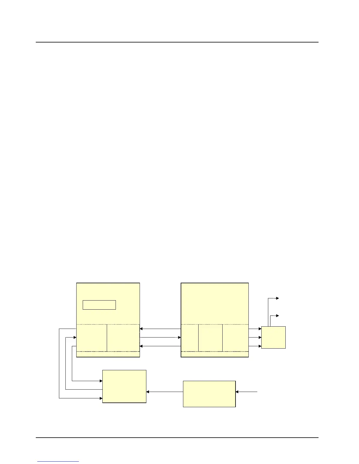
3.4.5 ASTRO Spectra Plus TX Signal Path
The transmit signal path (refer to Figure 3-17) follows some of the same design structure as the
receive signal path described in Section 3.4.4 ASTRO Spectra Plus RX Signal Path on page 3-41.
Figure 3-17. ASTRO Spectra Plus TX Signal Path
REF MOD
J501-48
MOD OUT
J501-49
PATRIOT
U300
DSP 56600
ADDAG
U201
FMOUTSFS
SCK
STD
Serial TX Data
48 kHz
2.4 MHz
SCKB
STDB
SC2B
CODEC
U402
FSR
MCLK
DT
SC2A
SCKA
SRDA
SAP BBP
TG
8 kHz
512 kHz
Data
Gain / Attenuation
Stages
U400,401,404
D/A
Conv.
OUTQB
OUTQ
U202
MAI
J501-39
 Loading...


