6881076C25-E September 5, 2008
Troubleshooting Procedures: Power Amplifier Procedures 4-31
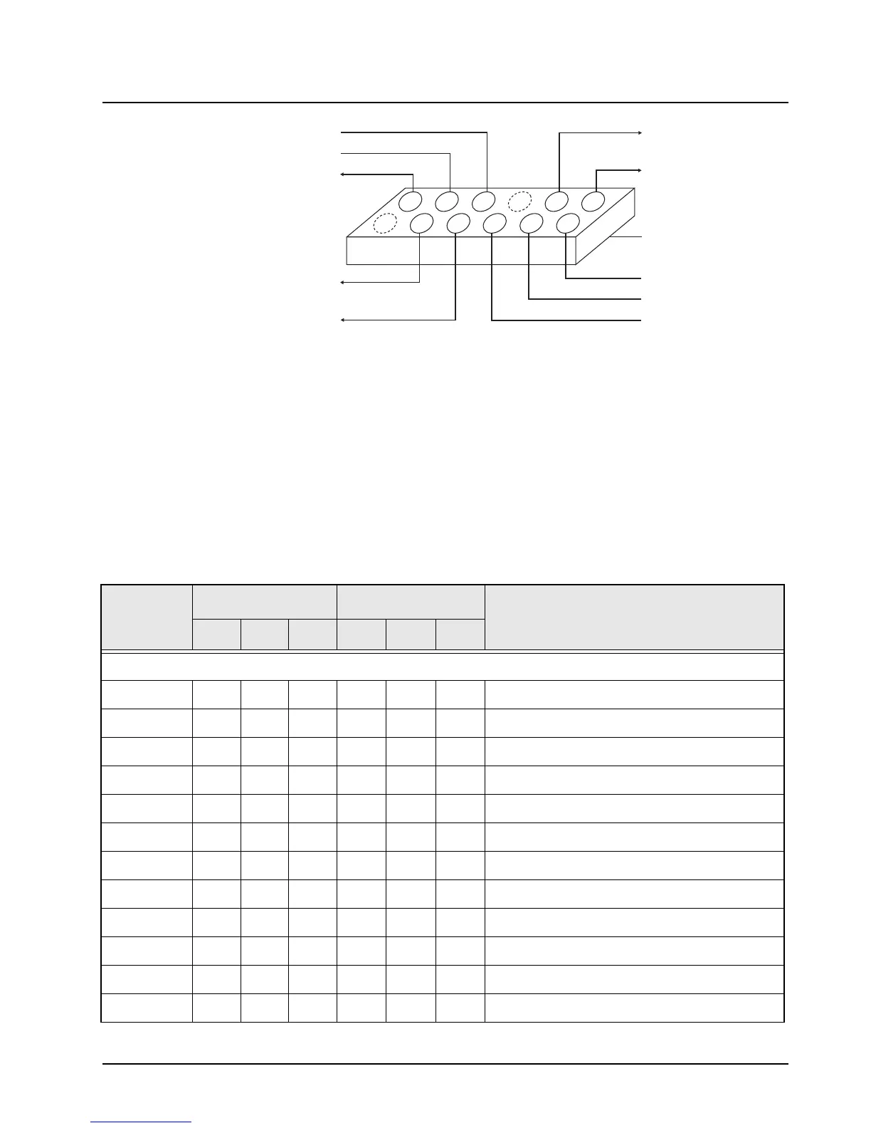
Figure 4-5. PA Test Adapter, 25/10 Watt Power Amplifier
4. With the applied control voltage drive initially at 0 V, slowly increase the voltage until power
out equals 28 Watts. Power should rise smoothly with control voltage once the turn-on
threshold is reached. Control voltage drive should not exceed 9.2 V.
5. If 9.2 V does not produce 28 Watts, then a failure exists in the power amplifier circuit.
6. Refer to the voltage chart (see Table 4-11). Measure the indicated voltages. If they are not
within the limits shown in the chart, then a failure exists in the PA assembly.
7. If the voltages in the chart are correct, verify that the injection is at least 10 mW. (See the
VCO troubleshooting section.)
8. If no failure is located from the previous checks, troubleshoot the power control circuitry.
Table 4-11. Power Control DC Voltage Chart
LOCATION
RX MODE TX MODE
COMMENTS
LOW TYP HI LOW TYP HI
P0853
1 ––––––
Key (no pin or wire)
2002.03.2
Control Voltage Limit
302.07.09.2
Control Drive Voltage
4 10.8 13.8 16.6 10.4 13.4 16.2
Current Sense +
50009.29.49.8
Keyed 9.4
6 10.8 13.8 16.6 10.4 13.4 16.2
A+ to Command Board
70 1.2
Temp Sense (cutback begins at 3.3 V)
8 ––––––
Key (no pin)
901.53.55.0
Forward Detect Volt
10 10.8 13.8 16.6 10.4 13.4 16.2
A+ to Command Board
11 9.4 9.6 9.9 9.4 9.6 9.9
9.6-V Supply from Command Board
12 10.8 9.8 13.1 15.9
Current Sense – (voltage delta 150 mV)
A+ TO COMMAND BOARD
CURRENT SENSE +
A+ TO COMMAND BOARD
CURRENT SENSE -
CONTROL VOLTAGE LIMIT
CONTROL VOLTAGE DRIVE
K9.4
FEMALE RECEPTACLE
CONNECTOR W 100 MIL
SPACING MATES TO P853
REGULATED 9.6V
V DETECT
TEMP SENSE
8
6
4
2
10
12
7
5
3
1
9
11
 Loading...


