September 5, 2008 6881076C25-E
3-10 Theory of Operation: Command Board
3.2.4 Regulators
The regulator circuits include an unswitched +5 V (UNSW5V) discrete circuit, and the regulator/
power-control IC (RPCIC) that produces switched +5 V (U500, pin 14) and 9.6 V (U500, pin 17).
The UNSW+5-V source is used by the RPCIC as a reference (U500, pin 20) for its switched + 5-V
source. This regulated voltage is produced from the A+ voltage and is present when the battery is
connected. The regulators within the RPCIC are controlled by the input to pin 24 via a digital
transistor, Q538. This device is controlled from an output (9.6/5-V enable) of the SIOIC (U522, pin
15).
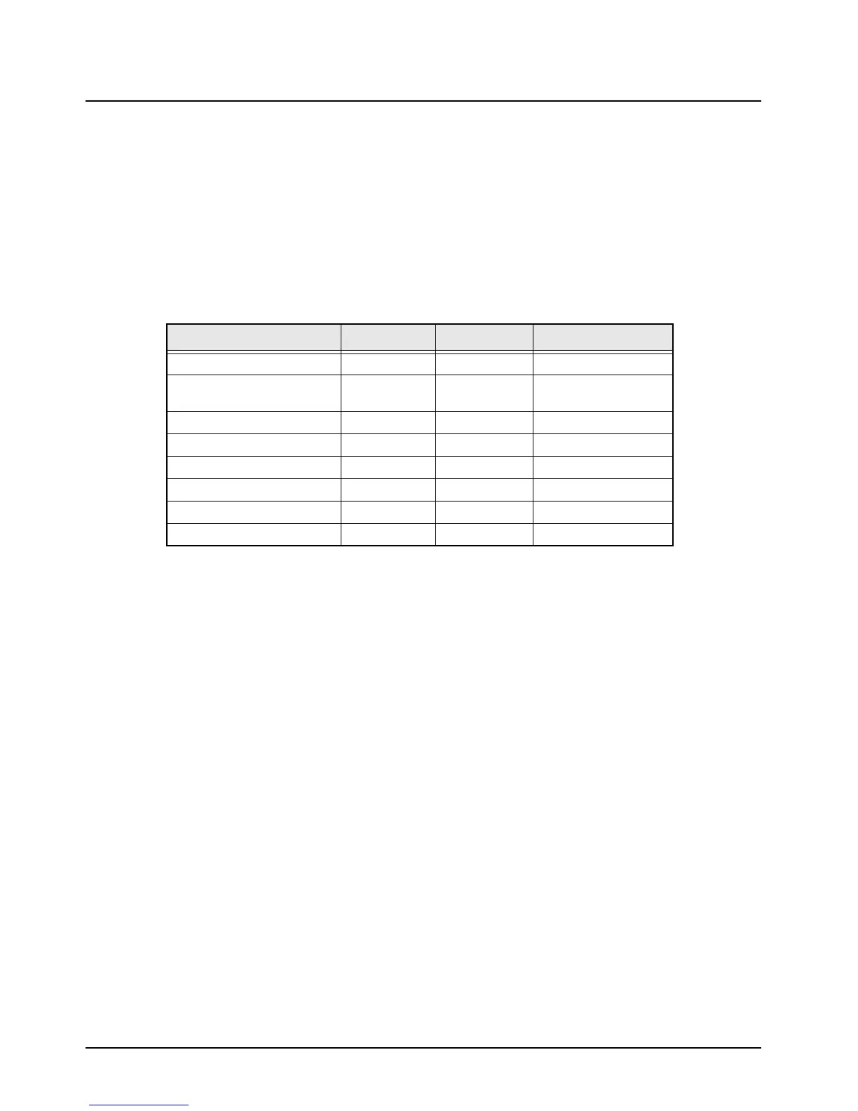
The various voltages used by the ICs on the command board are shown in Table 3-1.
3.2.5 Reset Circuits
The reset circuits consist of the power-on reset (POR), high-/low- battery voltage reset, and the
external bus system reset. The reset circuits allow the microcontroller to recover from an unstable
condition, such as no battery on the radio, battery voltage too high or too low, and remote devices on
the external bus not communicating.
When the battery (A+) is first applied to the radio, the unregulated voltage source powers the
unswitched +5-V regulator and the SIOIC internal regulator. The voltage is also sent to the control
head, where it is switched on/off by a series FET transistor. The transistor returns the voltage to the
command board, via connector P502-31, as switched B+. The switched B+ voltage is sensed by the
SIOIC on pin 28, and changes the state of the 9.6-V enable output gate (RPCIC_EN*) to an active
“low.” The low state turns on the 9.6-V regulator (U500-24), and its regulated output is fed back to
the input of the voltage comparator on the SIOIC (U522-14). The comparator output switches to a
logic low upon exceeding the 5.6-V threshold (see Figure 3-5 on page 3-11).
Table 3-1. Integrated Circuits Voltages
Integrated Circuit UNSW5V SW +5V SW +9.6V
Serial Input/ Output (SIOIC)
U522-6, -24 U522-3, -12 U522-14
Regulator/ Power Control
(RPCIC)
U500-20 U500-14 U500-17
Digital/ Analog IC (DAIC)
U502-1, -28
Analog Switch
U523-16, U524-14
RS232 Driver (IC)
U526-19
555 Timer (IC)
U501-8
8-Bit Shift Register
U530-16
Differential Amplifiers
U401-4, U402-4
 Loading...


