September 5, 2008 6881076C25-E
4-22 Troubleshooting Procedures: Power Amplifier Procedures
Begin troubleshooting by connecting an RF power meter and appropriate power load to the antenna
connector. Connect the control cable and the power cable. Make sure the ignition sense lead is also
connected to the positive lead of the power supply. Note that a regulated DC power supply capable
of at least 30 A. is necessary to power a high-powered Spectra transmitter. Remove the radio bottom
cover. Remove the PA shield by pulling straight up on the plastic handle. This must be done
carefully, as the edge of the PA shield can damage components on the PA board if it is removed
unevenly. Set the power supply to 13.4 V. The radio may now be turned on. All critical voltages may
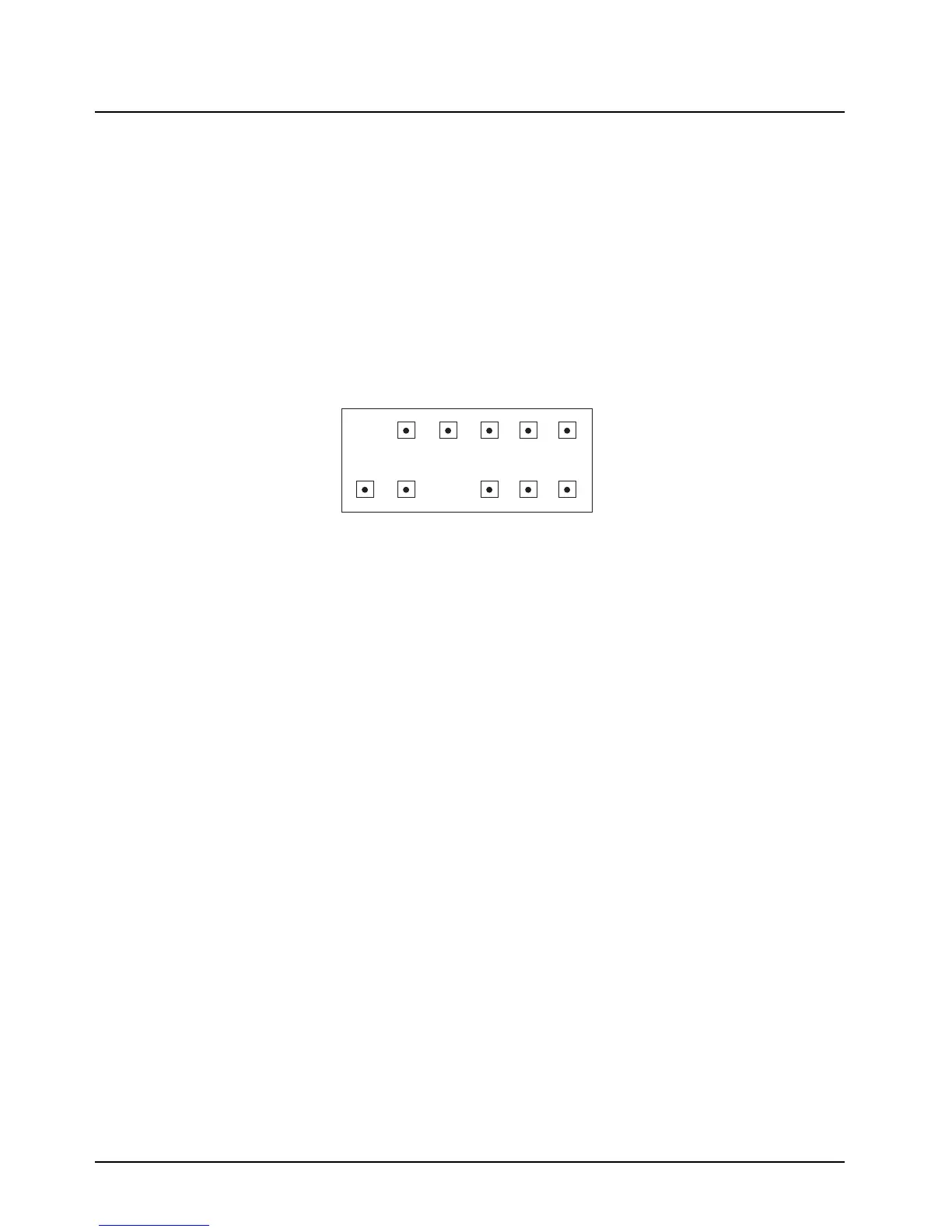
be measured at connector J1 from the top side of the PA board. A diagram of the connector pin-out,
as viewed from the top side of the PA board, is shown in Figure 4-4.
Figure 4-4. Connector Pin-Out – High-Power Amplifier
Key the transmitter. The RF power meter should read at least 100 Watts if it is calibrated. If power is
low, the power set must be checked first before suspecting a defective PA or command board. This
may be checked using a PC and RSS software. Alternatively, front panel programming may be used.
Please refer to the ASTRO Digital Spectra and Digital Spectra Plus Mobile Radios Basic Service
Manual (6881076C20) for programming instructions.
If correct power output can not be obtained by following the power set procedure outlined in the
ASTRO Digital Spectra and Digital Spectra Plus Mobile Radios Basic Service Manual
(6881076C20), it is possible that current limit may be improperly set. This can not be adjusted using
front panel programming. A PC with RSS must be used. A simple way to check for current limit
engagement is to temporarily short out the current sense resistor R3849 with a piece of 12- or
14- gauge wire. If full power is restored, then RSS must be used to properly set current limit.
12 10 8 6 4 2
11 9 7 5 3 1
Pin Configuration of J1
As Viewed From Top of PA Board
1 Control Voltage Limit
2 Control Voltage Drive
3 Current Sense +
4 Key 9.4V
5 Filtered A+
6 Temp-Sense
7 Not Connected
8 Forward Power Detect
9 9.6V
10 Current Sense –
11 Not Connected
12 10 8 6 4 2
11 9 7 5 3 1
Pin Configuration of J1
As Viewed From Top of PA Board
1 Control Voltage Limit
2 Control Voltage Drive
3 Current Sense +
4 Key 9.4V
5 Filtered A+
6 Temp-Sense
7 Not Connected
8 Forward Power Detect
9 9.6V
10 Current Sense –
11 Not Connected
12 Not Connected
 Loading...


