6881076C25-E September 5, 2008
Troubleshooting Procedures: Power Amplifier Procedures 4-51
Key the transmitter. The RF power meter should read at least 100 Watts if it is calibrated. Range 3
UHF radios will have power set to 78 Watts at modes above 470 MHz. R4 UHF radios will be set to
78 Watts on all modes. If power is low, the power set must be checked first before suspecting a
defective PA or command board. This may be checked using a PC and RSS software. Alternatively,
front panel programming may be used. Please refer to the ASTRO Digital Spectra and Digital
Spectra Plus Mobile Radios Basic Service Manual (6881076C20) for programming instructions.
If correct power output can not be obtained by following the power set procedure outlined in the
ASTRO Digital Spectra and Digital Spectra Plus Mobile Radios Basic Service Manual
(6881076C20), it is possible that current limit may be improperly set. This can not be adjusted using
front panel programming. A PC with RSS must be used. A simple way to check for current limit
engagement is to temporarily short out the current sense resistor R5875 with a piece of 12- or
14-gauge wire. If full power is restored, then RSS must be used to properly set current limit.
If it is verified that both power set and current limit are not related to the power problem, then the
synthesizer output must be checked. A milliwatt meter connected to the TX injection cable should
indicate at least 30 mW of injection power during key-up. If this is not the case, refer to the RF Board
and VCO troubleshooting procedures in this chapter.
If the command board and synthesizer are functioning properly, the PA must be defective. Details on
troubleshooting each circuit of the PA follow.
4.5.2.1.2 PA Functional Testing
NOTE: When setting or measuring RF power at UHF, follow these guidelines to avoid measurement
errors due to cable losses or non-50-ohm connector VSWR:
- All coaxial cables should be low loss and as short as possible.
- Attenuators and 50-ohm loads should have at least 25 dB return loss.
- Mini UHF to 'N' adapter, P/N 58803671321, should be used at the antenna connector. All
other connectors should be 'N' type. No other adapters, barrel connectors, etc. should be
used.
Maximum input level to the PA is 50 mW. Too much input power could result in damage to
the LLA stage.
44 2.1 3.2
Control AMP Reference
Q0500E 13.0 13.0
A+ - CR0500 Drop
Q0501C 12.3 12.3
VQ0500E - B/E Drop
Q0501E 0.2 0.2
V pin 23 - B/E Drop
Q0503E 0 1.5
V pin 42 - B/E Drop (TX)
Q0503C 13.6 9.0
Q0504B 13.6 12.9
A+ - B/E Drop (TX)
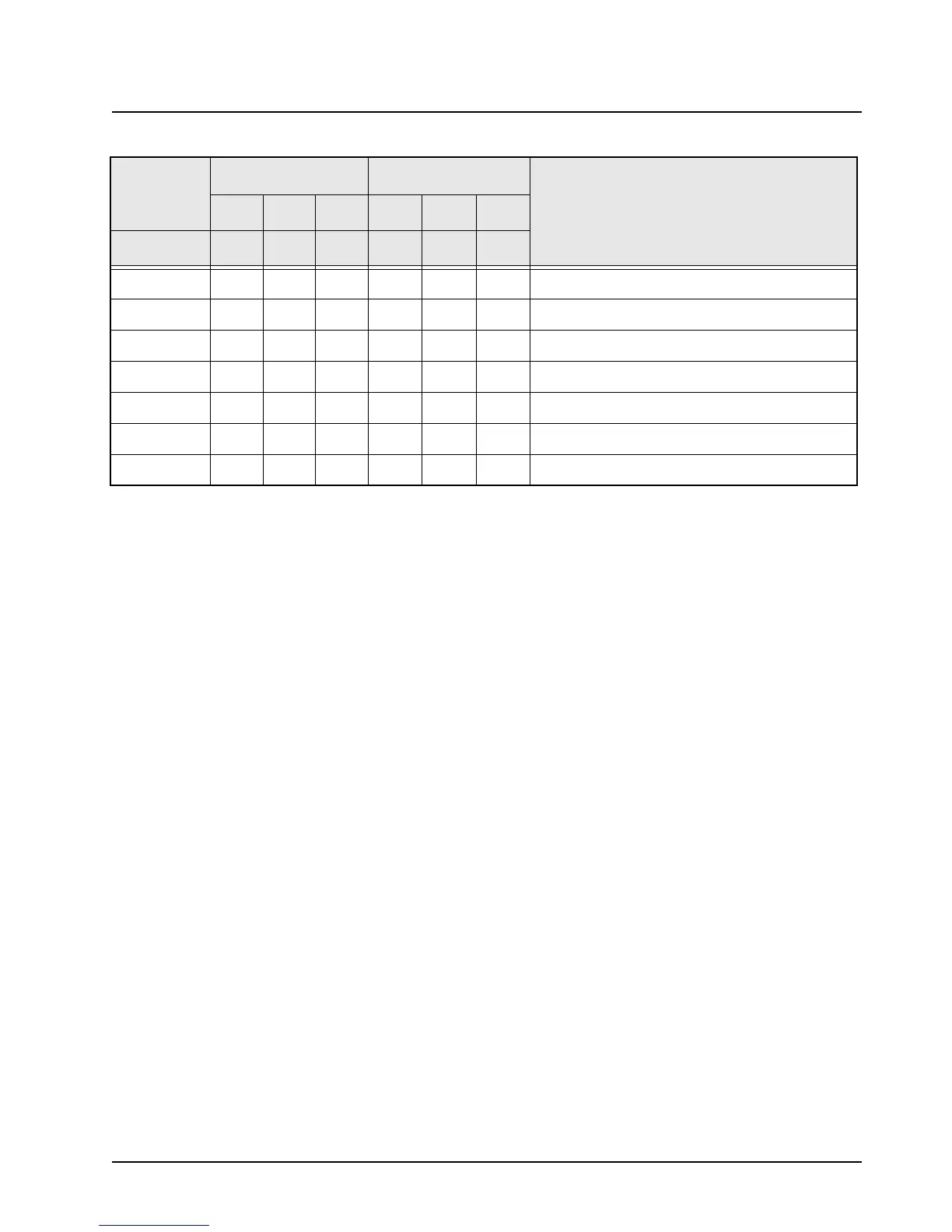
Table 4-17. Power Control DC Voltage Chart (Continued)
LOCATION
RX MODE TX MODE
COMMENTS
LOW TYP HI LOW TYP HI
J1
 Loading...


