Section 1: 3-1
6881091C63-F
Chapter 3
SERVICE AIDS
1.0 Recommended Service Tools
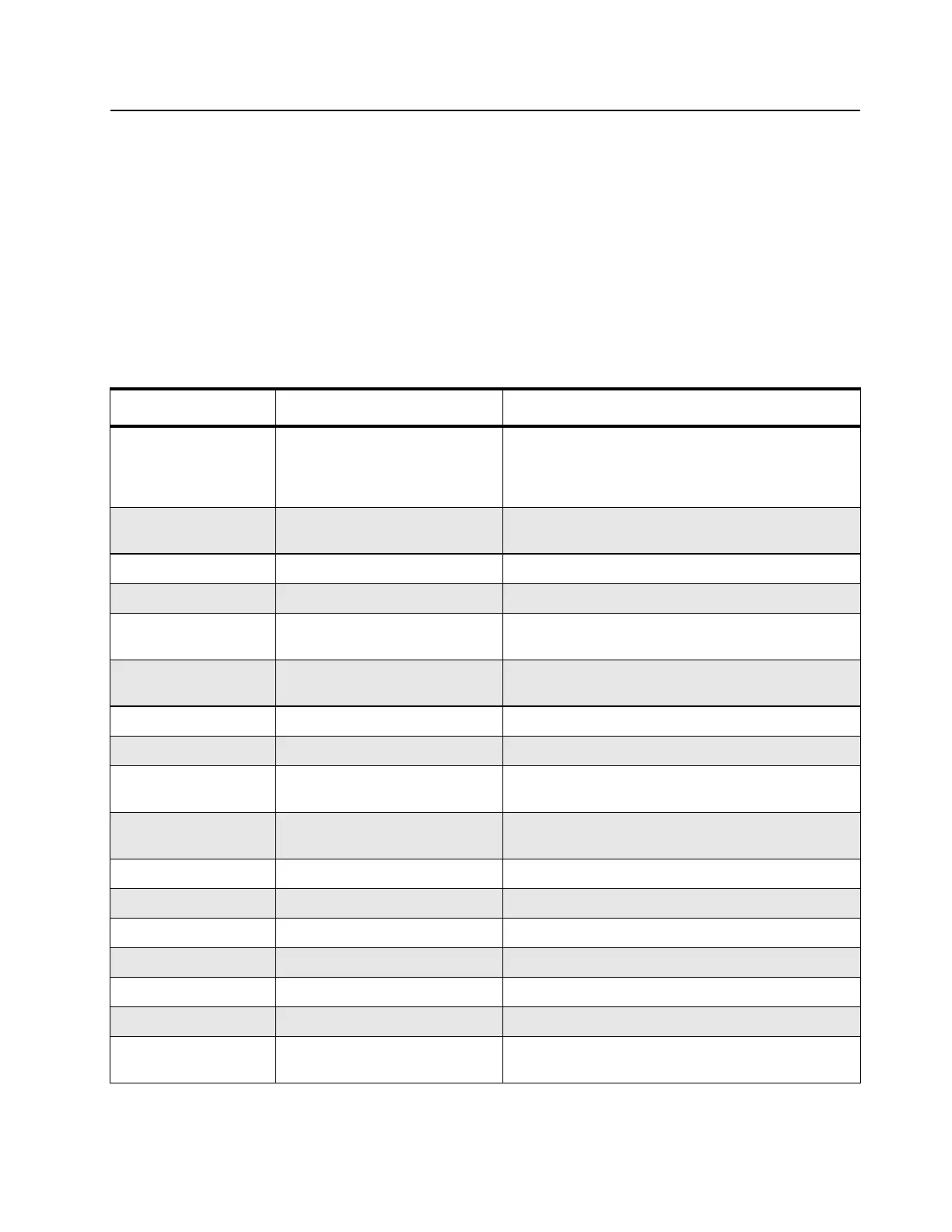
Table 3-1 lists the service tools recommended for working on the radio. While all of these items are
available from Motorola, most are standard workshop equipment items, and any equivalent item
capable of the same performance may be substituted for the item listed.
Table 3-1 Recommended Service Tools
Motorola Part No. Description Application
0180302E51
0180386A78
Master lens system
Illuminated magnifying glass
with lens attachment
Illumination and magnification of components
0180303E45 SMD tool kit (included with
R1319_)
-
0180357A57 Wall-Mounted Power Supply Used to supply power to the RIB (120 VAC)
0180358A56 Wall-Mounted Power Supply Used to supply power to the RIB (220 VAC)
0180386A82 Anti-static Grounding Kit Used during all radio assembly and disassembly
procedures
1010041A86 Solder (RMA type), 63/67,
0.5 mm diameter, 1 lb. spool
-
3080070N01 Programming Cable Connects RIB to radio microphone input
3080369B71 Computer Interface Cable Connects the RIB to the computer (25-pin)
3080369B72 Computer Interface Cable Connects the RIB to the computer 9-pin (Use for IBM
PC AT–other IBM models use the B71 cable above)
6680309B53 Rework equipment catalog Contains application notes, procedures, and technical
references used to rework equipment
6680384A98 Brush -
6684253C72 Straight prober -
6686119B01 Removal Tool Assists in the removal of radio control head
8180384J59 Housing Eliminator (short) Test fixture used to bench test the radio PCB
8180384J60 Housing Eliminator (medium) Test fixture used to bench test the radio PCB
8180384J61 Housing Eliminator (long) Test fixture used to bench test the radio PCB
8180384L95 Housing Eliminator (short + top) Test fixture used to bench test the radio PCB (radio
uses pressure pads to retain PCB)

 Loading...