Section 2: 2-1
6881091C63-F
Chapter 2
THEORY OF OPERATION
1.0 Introduction
This chapter provides a detailed theory of operation for the control head circuits. For troubleshooting
information, refer to the related section of this manual.
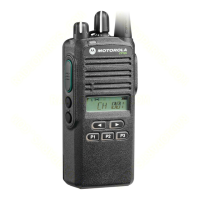
2.0 Control Head (CDM750 / PRO3100)
2.1 Power Supplies
The power supply to the control head is taken from the host radio’s FLT A+ voltage via connector
J0801, pin 3 and the regulated 5V via connector J0801 pin 7. The voltage FLT A+ is at battery level
and is used for the LEDs, the back light and to power up the radio using the On/Off/Volume knob.
The stabilized 5V is used for the µP and the keypad buttons. The voltage USW 5V derived from the
FLT A+ voltage and stabilized by the series combination of R0822, VR0822 is used to buffer the
internal RAM of the µP (U0831). C0822 allows the battery voltage to be disconnected for a couple of
seconds without losing RAM parameters. Dual diode D0822 prevents radio circuits from discharging
this capacitor. When the supply voltage is applied to the radio, C0822 is charged via R0822 and
D0822. To avoid the µP entering the wrong mode if the radio is switched on while the voltage across
C0822 is still too low, the regulated 5V supply charges C0822 via diode D0822.
2.2 Power On/Off
The On/Off/Volume knob, when pressed, switches the radio’s voltage regulators on by connecting
line ON OFF CONTROL to line UNSW 5V via D0821. Additionally, 5V at the base of digital transistor
Q0822 informs the control head’s µP about the pressed knob. The µP asserts pin 62 and line CH
REQUEST low to hold the line ON OFF CONTROL at 5V via Q0823 and D0821. The high line ON
OFF CONTROL also informs the host radio that the control head’s µP wants to send data via the
SBEP bus. When the radio returns a data request message, the µP informs the radio about the
pressed knob. If the radio is switched off, the radio’s µP switches it on and vice versa. If the
On/Off/Volume knob is pressed while the radio is on, the software detects a low state on line ON
OFF SENSE, the radio is alerted via line ON OFF CONTROL and sends a data request message.
The control head µP informs the radio about the pressed knob and the radio’s µP switches the radio
off.
2.3 Microprocessor Circuit
The control head uses the Motorola 68HC11E9 µP (U0831) to control the LEDs and to communicate
with the host radio. RAM and ROM are contained within the µP.
The µP generates its clock using the oscillator inside the µP along with a 8 MHz ceramic resonator
(U0833) and R0920.
NOTE
From this point on the microprocessor is referred to as “µP”.

 Loading...