Troubleshooting Flow Chart for 45 W Transmitter Section 11: 3-3
6881091C63-F
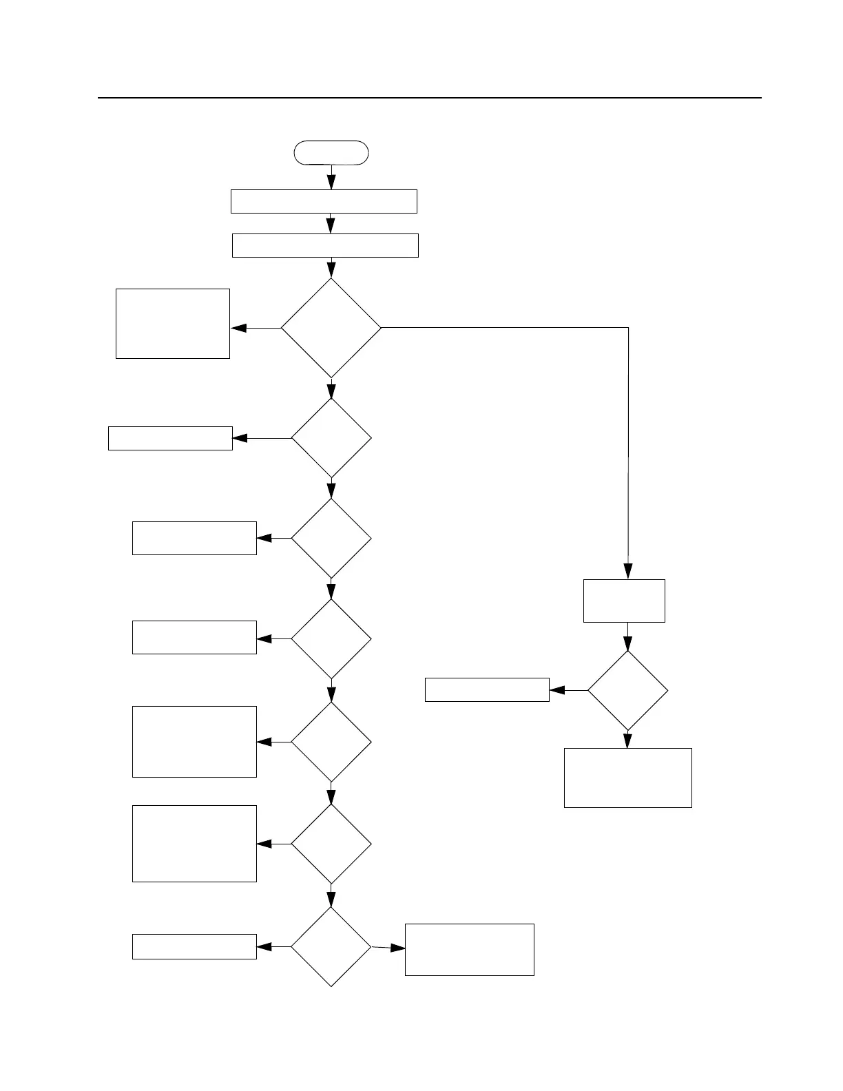
2.0 Troubleshooting Flow Chart for 45 W Transmitter (Sheet 1 of 3)
Measure
supply
current
increase
when keyed
NO
YES
START
Check if pressure pad closes S3440
Check components be-
tween Q3441 and RF
output, antenna switch
D3471, D3472, Q3472,
VR3471, Q3471
>500mA & <4A
>4A
<500mA
Check PA stages
Is control
voltage at
TP3402
>1V when
keyed?
Is PCIC
U3501 Pin 14
9.3V DC?
Short TP3403
to Ground
NO
YES
Is voltage at
TP3402
raised?
Check PA stages
YES
YES
Check 9.3 V Regulator
U0641
NO
YES
Is PCIC
U3501 Pin 16
>4V DC?
Replace PCIC
U3501
NO
YES
Is TP3404
9.1V DC?
If U3201 Pin 2 is high,
replace PCIC U3501;
otherwise check con-
troller and FGU
YES
NO
Is TP3403
>0.5V DC?
Replace PCIC U3501
Check power-sensing
circuitry (D3451 & D3452)
Check power-sensing
circuitry (D3451 & D3452)
NO
YES
Is PCIC
U3501 Pin 5
> 1V DC?
Check power setting,
tuning & components
between PCIC Pin 5
and ASFIC (U0221)
Pin 4 before replacing
ASFIC
No power or low power when keyed

 Loading...