EasyManuals Logo

Motorola CDM1250 Service Manual

Motorola CDM1250
686 pages
To Next Page IconTo Next Page
To Previous Page IconTo Previous Page
Page #349 background imageLoading...
Page #349 background image
Troubleshooting Flow Chart for Transmitter Section 7: 3-3
6881091C63-F
2.0 Troubleshooting Flow Chart for Transmitter
No
DC Voltage
@ Gate of
Q1401
No
Yes
START
No or Low
TX
DC Voltage
@Drains of
Q1402 &
Q1403
@ Cathode of
D1401 &
D1402
DC Voltage
Drains of Q1402 &
AC Voltages @
Q1403 both sine or
both distorted
Check 9T1 and
Diode Bias Circ
u
Verify RF Contin
u
to gates of
Q1402 & Q140
3
Check circuitry
between Q1402
&
Q1403 and
Antenna Port
Check
MOSBIAS_1
Supply and
Feed Network
No
<<18V p
p
Yes
No
Yes
< 1 A
No
Check
Q1401
Device
Yes
CURRENT
RF @
Junction
R1413 &
DC Voltage
@ TP1402 &
TP1403
Yes
Check
MOSBIAS_2
MOSBIAS_3
and Feed Networ
k
Check DC/AC
Gate Circuits
of Q1402 & Q1403
Check Supply Fee
and/or Power Con
t
Circuits.
No
>18V p
p
Check
U1401
Device
AC Voltag
e
@ Gate of
Q1401
Ye
s
DC Voltage
@ U1401
Ye
s
No
Power Out
> 1 A
Look for
short on
Supply Lin
e
Check Pressure Pad
and/or
Switch Circuitry
Yes
No
TX
Safety
Switch
R1414

Table of Contents

Other manuals for Motorola CDM1250

Questions and Answers:

Question and Answer IconNeed help?

Do you have a question about the Motorola CDM1250 and is the answer not in the manual?
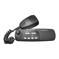
Motorola CDM1250 Specifications

General IconGeneral
DisplayAlphanumeric
IP RatingIP54
Frequency RangeVHF: 136-174 MHz, UHF: 403-470 MHz
SignalingPL, DPL, MDC1200, Quick Call II
Operating Temperature-22°F to +140°F (-30°C to +60°C)
Power OutputVHF: 1-25W; UHF: 1-25W

Related product manuals