Section 6: 2-1
6881091C63-F
Chapter 2
THEORY OF OPERATION
1.0 Introduction
This chapter provides a detailed theory of operation for the UHF circuits in the radio. For details of
the theory of operation and troubleshooting for the associated controller circuits refer to the
controller section of this manual.
2.0 UHF Band 2 (450–512/527 MHz) 1–25W Receiver Front-End
2.1 Receiver Front-End
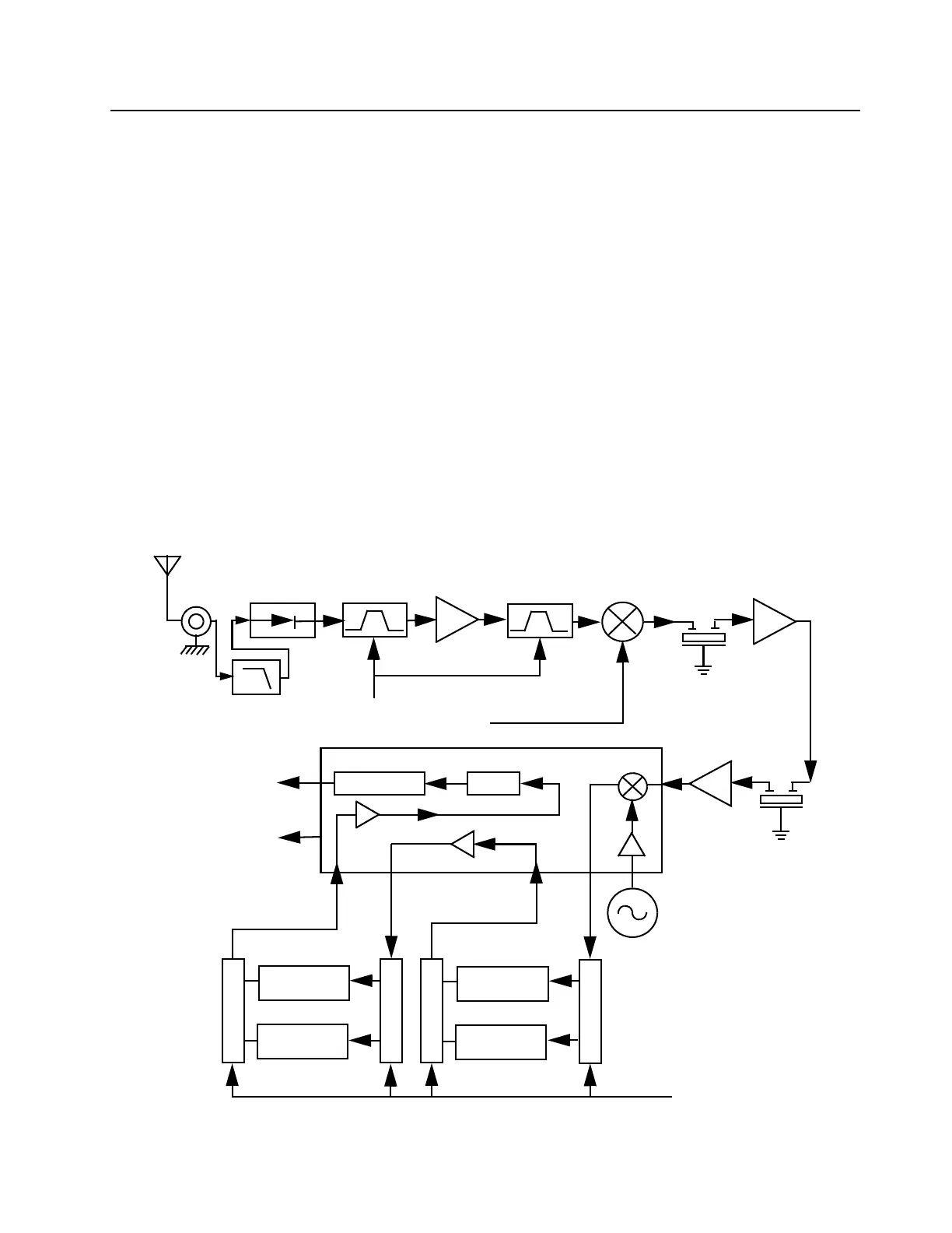
The receiver is able to cover the UHF range from 450 to 512 MHz (for CDM models) and from
450 to 527 MHz (for PRO models). It consists of four major blocks: front-end bandpass filters and
pre-amplifier, first mixer, high-IF, low-IF and receiver back-end. Two varactor-tuned bandpass filters
perform antenna signal pre-selection. A passive double-balanced mixer converts the signal to the
first IF of 44.85 MHz. Low-side first injection is used.
Figure 6-1 UHF Receiver Block Diagram
Demodulator
1. Crystal
Filter
Mixer
Varactor
Tuned Filter
RF Amp
Varactor
Tuned Filter
Pin Diode
Antenna
Switch
RF Jack
Antenna
Control Voltage
from PCIC
First LO
from FGU
Recovered Audio
RSSI
Second LO
2. Crystal
Filter
455kHz Filter
(25kHz)
455kHz Filter
(25kHz)
455kHz Filter
(12.5kHz)
455kHz Filter
(12.5kHz)
Switch
Switch
Switch
Switch
Limiter
1. IF Amp
2. IF Amp
Filter Bank Selection
from Synthesizer IC
Harmonic
Filter
BWSELECT

 Loading...