Section 3: 3-1
6881091C63-F
Chapter 3
CONTROLLER SCHEMATICS AND PARTS LISTS
1.0 Allocation of Schematics and Circuit Boards
1.1 Controller Circuits
This chapter shows the schematics and the parts lists for the controller circuits.
1.2 Voice Storage Facility
The Voice Storage facility is an orderable option on all CDM and PRO models except the PassPort
model (CDM1550•LS+), on which Voice Storage is a standard feature.
The schematics (including the Voice Storage schematic, where applicable), boards and parts lists
for these circuits are shown in this chapter.
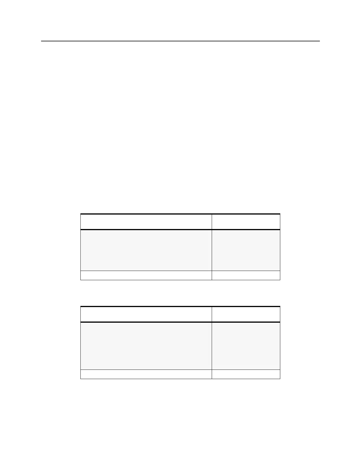
Table 3-1 Controller T2 Diagrams and Parts Lists
Controller T2 used on PCB:
8486172B04 VHF, 1–25 W
SCHEMATICS
Controller Overall
Supply Voltage
Audio
I/O
Microprocessor
Page:
3: 3-5
3: 3-6
3: 3-7
3: 3-8
3: 3-9
Parts List 3: 3-10
Table 3-2 Controller T5 Diagrams and Parts Lists
Controller T5 used on PCB:
8486172B06 VHF, 1–25 W
SCHEMATICS
Controller Overall
Supply Voltage
Audio
I/O
Microprocessor
Voice Storage (if fitted)
Page:
3: 3-12
3: 3-13
3: 3-14
3: 3-15
3: 3-16
3: 3-17
Parts List 3: 3-18

 Loading...