Chapter 5 Laser Unit
5.2 C-LU2 Two-laser Unit, and C-LU3 Three-laser Unit
1-106
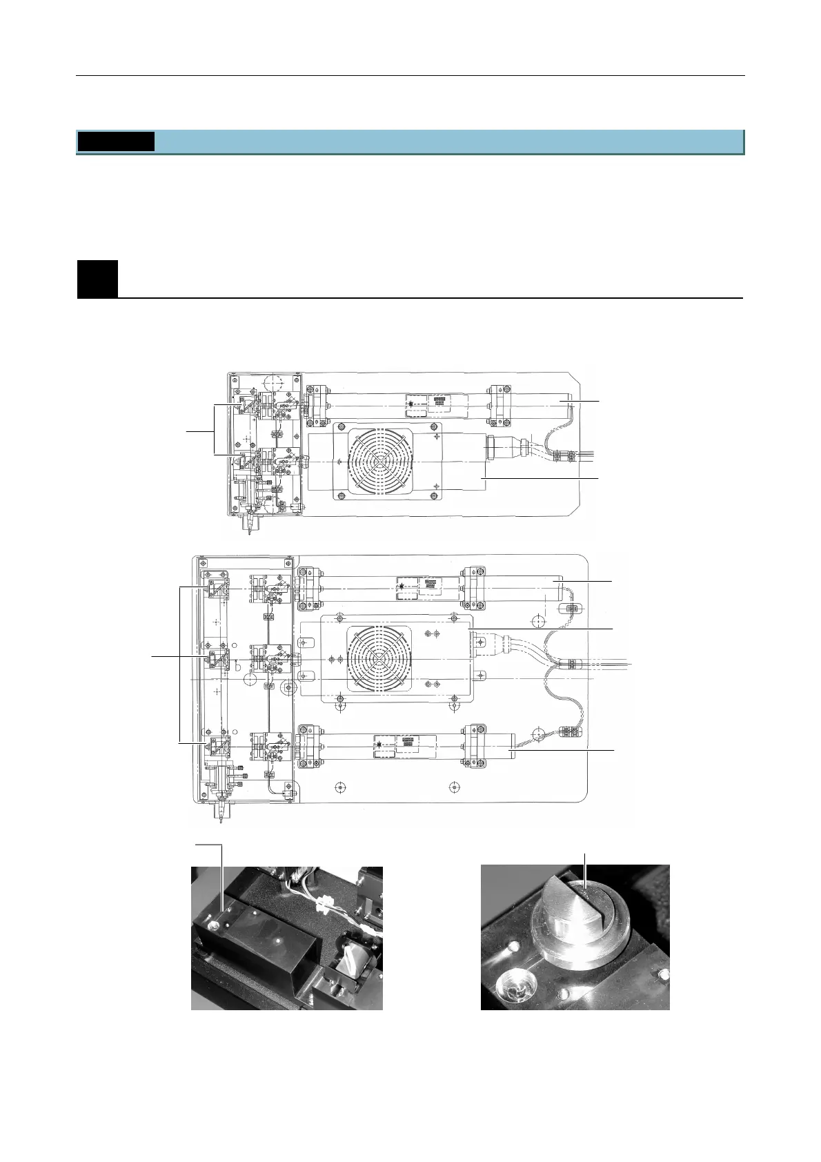
5.2.3 Laser Rough Adjustment
Determine the position of the argon laser by using the optical axis of the farthest He-Ne laser (He-Ne1 laser in
Figure 5.2-3 or in Figure 5.2-4) as the reference. Align the lasers so that their laser beams can be transmitted
through the optical fiber for the excitation light.
1
Setting up the dichroic mirror centering tool
Remove the dichroic mirrors and mount the dichroic mirror centering tool (see Figure 5.2-5). Install the
lasers so that their incident points are on the tool.
After the dichroic mirror of the He-Ne2 laser
has been removed
Figure 5.2-5
Pinhole for mounting
the dichroic mirror
centering tool
Dichroic mirror centerin
tool
Remove the
dichroic mirrors
He-Ne1
Remove
the dichroic
mirrors.
He-Ne2
r
He-Ne1
Figure 5.2-3
Figure 5.2-4

 Loading...