Chapter 6 Connection between the Laser Unit and the Microscope
6.4 Cable Connections (Four Laser Module A)
2-63
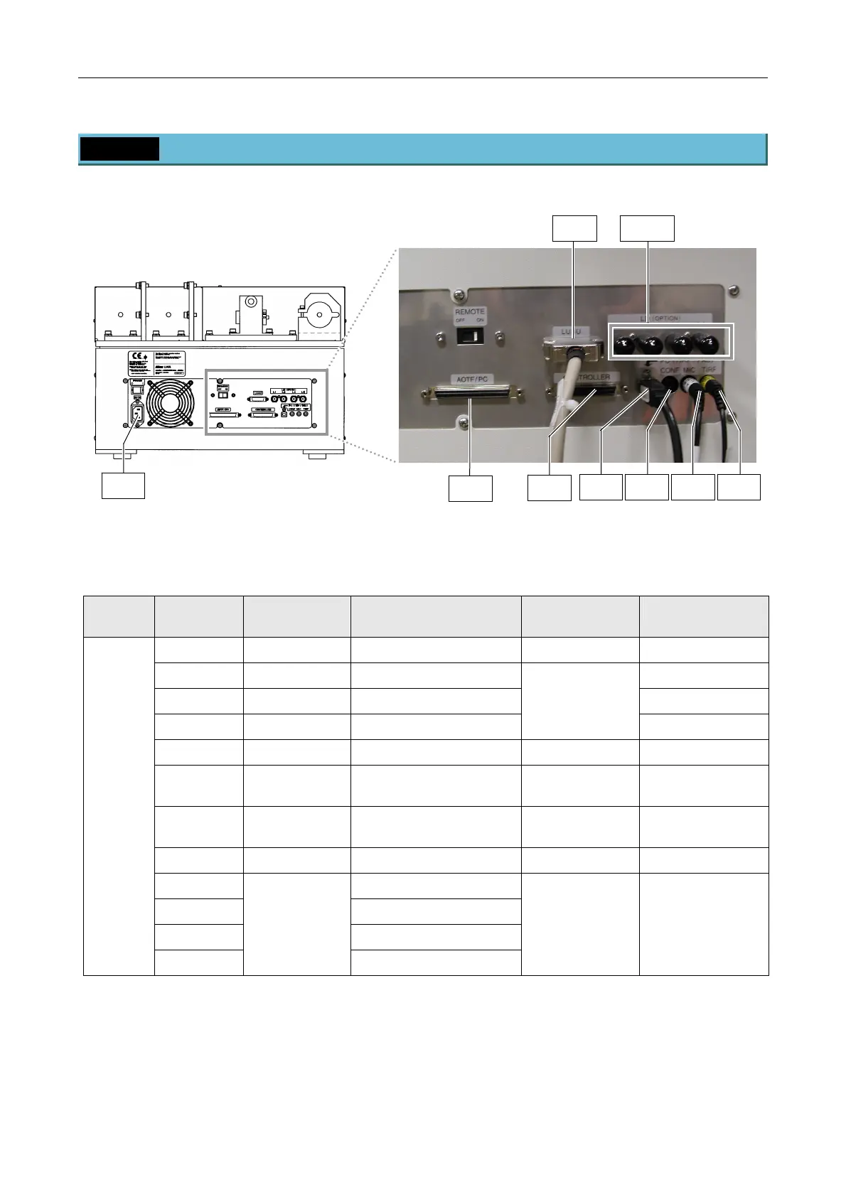
6.4 Cable Connections (Four Laser Module A)
Connect cables between units, as shown in Figure 6.4-1 and Table 6.4-1.
Figure 6.4-1 LU4A 4 laser module A
Table 6.4-1 Table of Cable Connections
Unit Connector
No.
Connector
Name
Connect to
(Name)
Connector Remarks
4LA1 AC IN AC power inlet
4LA2 AOTF/PC Do not use. Power control
4LA3 CONTROLLER Do not use. Shutter control
4LA4 CONF Do not use.
Refer to the
respective
instruction
manual.
Interlock signal
4LA5 MIC Microscope Interlock switch
4LA6 TIRF Laser safety cover
Supplied with the
TI-LU4SU
4LA7 LUSU
TI-LU4SU Shutter Unit
LU4
Supplied with the
TI-LU4SU
4LA8 PC(TIRF-PAU) PC USB cable
L1 (For future expansion)
L2 (For future expansion)
L3 (For future expansion)
Four
laser
module A
L4
LD(OPTION)
(For future expansion)
Do not use. Do not use in this
system. Otherwise,
a malfunction
occurs.
4LA7
4LA1
L1 to L4
4LA2
4LA6
4LA5
4LA4
4LA8
4LA3

 Loading...