Chapter 1 System Configurations and Part Names
1.2 Optical Paths of Lasers
1-18
1.2 Optical Paths of Lasers
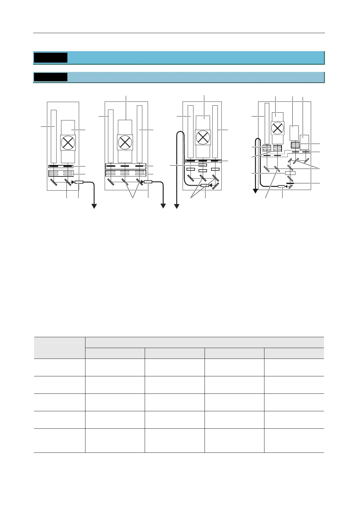
1.2.1 Laser Unit
Figure 1.2-1
(1) Laser mounting position L1
(See the table below.)
(2) Laser mounting position L2
(See the table below.)
(3) Laser mounting position L3
(See the table below.)
(4) Laser mounting position L4
(See the table below.)
(5) Motorized shutters
(6) ND filters (ND4 and ND8)
(7) Laser coupling mirror
(8) Laser outlet (single-mode optical fiber)
(9) Wavelength selection filter
(optional for C-LU3EX)
(10) AOTF brightness adjustment part
(11)
*1
ND filters (two ND32s)
(12)
*1
ND filters (ND2 and ND4)
*1: Installed only when the N-STORM kit is
mounted
Table 1.2-1
Laser mounting position
Model name
L1 L2 L3 L4
C-LU2
two-laser unit
405 nm to 514 nm 532 nm to 640 nm — —
C-LU3
three-laser unit
405 nm to 445 nm
594 nm to 645 nm
488 nm to 514 nm
532 nm to 561 nm
633 nm
—
C-LU3EX
three-laser unit EX
405 nm to 445 nm
594 nm to 645 nm
488 nm to 514 nm
532 nm to 561 nm
633 nm
—
LU4A
four-laser module A
630 nm to 650nm 400 nm to 445 nm 455 nm to 515 nm 540 nm to 595 nm
LU4A
four-laser module A
(for N-STORM)
635 nm to 648 nm 400 nm to 445 nm 455 nm to 515 nm 540 nm to 595 nm
C-LU3EX three-laser unit EXC-LU3 three-laser unitC-LU2 two-laser unit LU4A four-laser module A
(2)
(1)
(5)
(6)
(3)
(7)
(1)
(5)
(2)
(8) (7)
(3)
(5)
(9)
(8)
(7)
(6)
(8)
(2)
(1)
(4)
(3)
(2) (1)
(5)
(10)
(7)
(8)
(7)
(11)
(12)
1
(11)
(5)

 Loading...