Chapter 5 Laser Unit
5.4 LU4A Four-laser Module A
1-156
5.4 LU4A Four-laser Module A
The setup procedure for the LU4A four-laser module A is described below.
* The procedures on how to setup the previous LU4 model of the four-laser module are described in this
section. It is also possible to use this system in combination with the new LU4A four-laser module A.
5.4.1 Preparation
5.4.2 Laser Installation
5.4.3 Laser Rough Adjustment 1
5.4.4 Laser Rough Adjustment 2
5.4.5 Final Adjustment for the Ar Laser Light with the Optical Fiber
5.4.6 Final Adjustment for Other Laser Light with the Optical Fiber
5.4.7 Removing the AOTF Driver Remote Controller
5.4.8 Attaching the Sheet Metal Cover
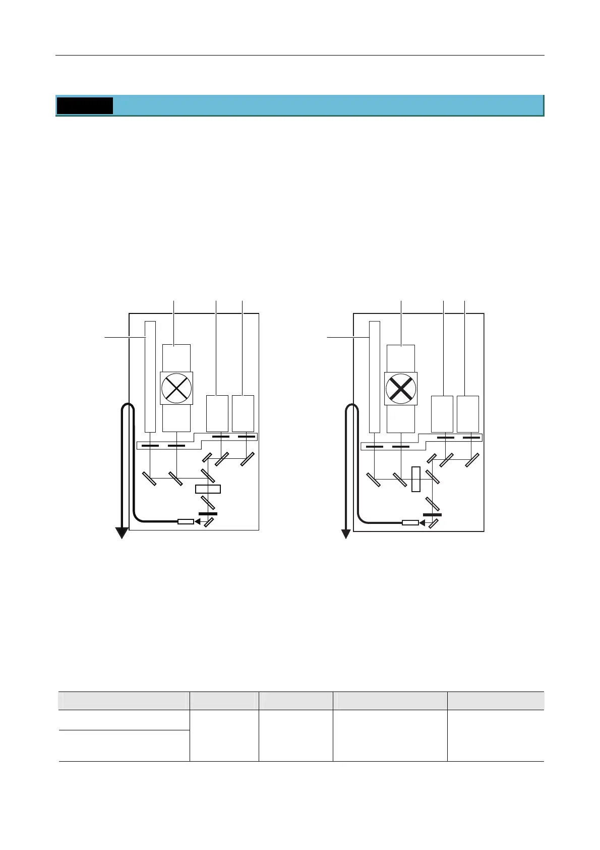
Figure 5.4-1
(1) L1 (See the table below.)
(2) L2 (See the table below.)
(3) L3 (See the table below.)
(4) L4 (See the table below.)
Table 5.4-1
L1 L2 L3 L4
LU4A Four-laser Module A
LU4 Four-laser Module
638-nm laser
(red)
647-nm laser
405-nm laser
440-nm laser
*
1
Ar laser (single line or
multiple lines) or 488-nm
solid-state laser
HeNe laser (green) or
561-nm solid-state
laser
594-nm solid laser
*
1
*1: Mountable only to the LU4A. The filter settings must be done manually.
(1)
(4)
(3) (2)
(1)
(4)
(3)
(2)
LU4A
LU4
(Do not use in this system.)

 Loading...