Home
Nikon
Laboratory Equipment
Eclipse TI-TIRF-E
Nikon Eclipse TI-TIRF-E User Manual
4
of 1
of 1 rating
329 pages
Give review
Manual
Specs
To Next Page
To Next Page
To Previous Page
To Previous Page
Loading...
Chapter 1
System Configuratio
ns and Part Names
1.3
Safety Labels and Opening
s
1-30
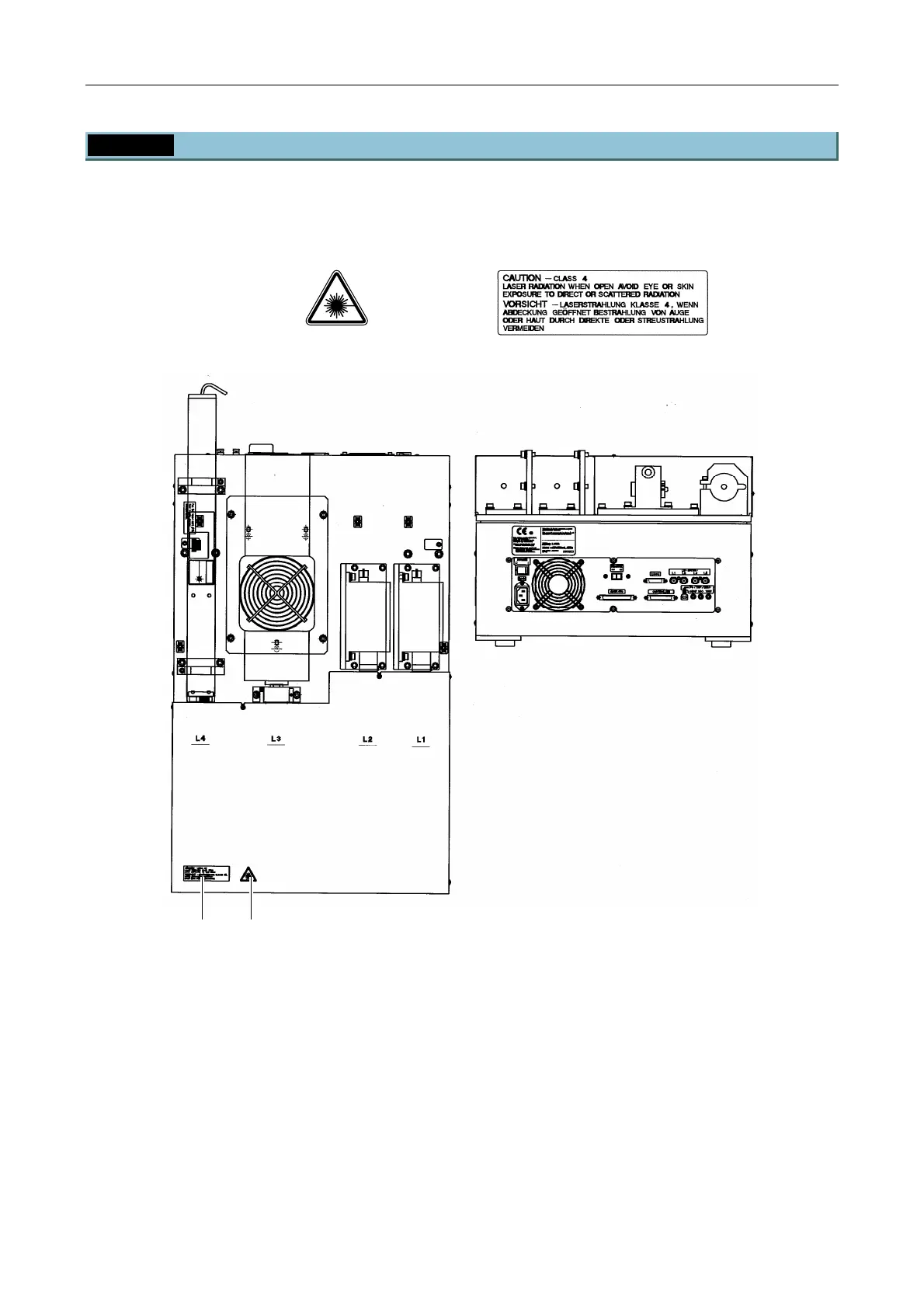
1.3.7
LU4A Four-laser Module A
Make sure that the labels are affixed in place.
(1) IEC
w
arning
label
-
laser hazard symbol
(12)
IEC caution l
abel - Class 4
area
Figure 1.3-7
* For the laser path inside the laser u
nit, see Section 1.2.1, “Laser Unit.”
(12)* (1)
43
45
Table of Contents
Default Chapter
15
Table of Contents
15
Overview
18
TIRF Illuminator Unit and Ti-U System Overview
18
Motorized TIRF Illuminator Unit and Ti-E System Overview
22
Motorized TIRF Illuminator Unit, LU4A, N-STORM, and Ti-E System Overview
26
TI-PAU Photo Activation Illuminator Unit and Ti-U System Overview
28
Optical Paths of Lasers
32
Laser Unit
32
Microscope Part (TIRF Illuminator Unit and Ti-U System)
33
Microscope Part (Motorized TIRF Illuminator Unit and Ti-E System)
34
Microscope Part (Photo Activation Illuminator Unit and Ti-U System)
36
Safety Labels and Openings
37
Ti-U Microscope Body (with the TIRF Illuminator Unit)
38
Ti-E Microscope Body (with the Motorized TIRF Illuminator Unit)
39
Ti-U Microscope Body (with the TI-PAU Photo Activation Illuminator Unit)
40
C-LU2 Two-Laser Unit
41
C-LU3 Three-Laser Unit
42
C-LU3EX Three-Laser Unit EX
43
LU4A Four-Laser Module a
44
LU-LR Four-Laser PS Rack
45
TI-LUSU Shutter Unit
46
TI-LU4SU Shutter Unit LU4
48
TI-TIRF TIRF Illuminator Unit
50
TI-TIRF-E Motorized TIRF Illuminator Unit - for Normal Microscopy
51
(Except N-STORM)
51
TI-TIRF-E Motorized TIRF Illuminator Unit - for N-STORM Microscopy
52
TI-PAU Photo Activation Illuminator Unit
53
Name of each Part
54
TIRF Illuminator Unit and Ti-U System
54
Motorized TIRF Illuminator Unit and Ti-E System
59
Motorized TIRF Illuminator Unit, LU4A, N-STORM and Ti-E System
63
TI-PAU Photo Activation Illuminator Unit and Ti-U System
68
Laser Unit
68
Laser Safety Kit
70
Related Product
78
2 Preparations
81
Check Items and Tools
81
Required Items
81
Tools
82
Overview of Setup Procedure
83
3 Setting up the PC and Operation Software
84
4 Setting up the Microscope
85
4.1 List of Parts
86
Setup Procedure
88
Assembling each Part and Attaching Them to the Microscope
88
Attaching the N-STORM Kit
99
Attaching the Laser Safety Kit
101
Attaching the Stage up Kit
103
Attaching the Back Port Unit
106
5 Laser Unit
107
Overview of the Laser Units
108
AOM Controller (Optional)
114
LU-LR Four-Laser PS Rack
115
C-LU2 Two-Laser Unit, and C-LU3 Three-Laser Unit
117
Preparation
117
Laser Installation
118
Laser Rough Adjustment
120
Final Adjustment for the Ar Laser Light with the Optical Fiber
127
Final Adjustment for the He-Ne Laser Light and 405 Laser Light with the Optical Fiber
133
Attaching the Sheet Metal Covers
135
C-LU3EX Three-Laser Unit EX
136
Preparation
137
Laser Installation
139
Laser Rough Adjustment 1
142
Laser Rough Adjustment 2
142
Final Adjustment for the Ar Laser Light with the Optical Fiber
160
Final Adjustment for the He-Ne Laser Light and 405 Laser Light with the Optical Fiber
166
Adjusting the AOM Controller (When the AOM Unit Used Only)
168
Attaching the Sheet Metal Cover
169
LU4A Four-Laser Module a
170
Preparation
170
Laser Installation
175
Laser Rough Adjustment 1
185
Laser Rough Adjustment 2
185
Final Adjustment for the Ar Laser Light with the Optical Fiber
203
Final Adjustment for Other Laser Light with the Optical Fiber
208
Removing the AOTF Driver Remote Controller
210
Attaching the Sheet Metal Cover
211
Setting up the LU-LR Four-Laser PS Rack
212
System Description
212
Mounting Laser Power Supply
215
Details on Mounting Laser Supply
221
6 Connection between the Laser Unit and the Microscope
227
Setting and Connecting the TI-LUSU Shutter Unit
227
Control System Selection
228
Control Mode of the Shutter Unit
228
Setting and Connecting the TI-LU4SU Shutter Unit LU4
229
DIP Switch Settings
231
Communications Commands
233
Attaching the Optical Fiber to the Light Source
236
Replacement of Optical Path Switch Mirror
238
Installing the N-STORM Kit
240
7 Confirmation and Check Sheet
242
Checking Procedure
242
Check Sheet
243
8 Specifications and Performance
245
Overall Configuration
245
TIRF Illuminator Unit / Motorized TIRF Illuminator Unit- Configuration for Normal Microscopy (Except N-STORM)
245
Motorized TIRF Illuminator Unit - Configuration for N-STORM
246
Photo Activation Illuminator Unit
248
Mountable Lasers
249
TI-LUSU Shutter Unit
252
AC Adapter for the TI-LUSU Shutter Unit
252
Power Cord for the AC Adapter of the TI-LUSU Shutter Unit
252
Environmental Conditions
253
Normal Microscopy (Except N-STORM)
253
N-Storm
253
Safety Standards Compliance
254
Normal Microscopy (Except N-STORM)
254
N-Storm
255
Overview
261
Optical Paths of Lasers
263
Laser Unit
263
Microscope Part (TIRF-PAU Illuminator and Ti-E System)
264
Safety Labels
265
Ti-U Microscope Body
266
Ti-E Microscope Body
267
LU4A Four-Laser Module a (with LU4-B5 Beamsplitter 50/50 Installed)
268
LU-LR Four-Laser PS Rack
269
TI-LU4SU Shutter Unit LU4
270
TIRF-PAU Illuminator
271
Name of each Part
272
Preparations
283
Check Items and Tools
283
Overview of Setup Procedure
284
Setting up the PC and Operation Software
285
Setting up the Microscope
286
Overall Configuration
286
Setup Procedure
287
Assembling each Part and Attaching Them to the Microscope
287
Attaching the Laser Safety Kit
295
Attaching the Stage up Kit
297
Attaching the Back Port Unit
300
Laser Unit
302
Overview of the Laser Units
303
LU4A Four-Laser Module a (with LU4-B5 Beamsplitter 50/50 Installed)
303
LU-LR Four-Laser PS Rack
307
Installation of the LU4-B5 Beamsplitter 50/50 (TIRF-PAU System)
309
Preparation
309
Connection between the Laser Unit and the Microscope
314
Setting and Connecting the TI-LU4SU Shutter Unit LU4
314
Attaching the Optical Fiber to the Light Source
317
Replacement of Optical Path Switch Mirror
319
Cable Connections (Four Laser Module A)
321
Confirmation and Check Sheet
322
Checking Procedure
322
Check Sheet
323
Specifications and Performance
325
Overall Configuration
325
4
Based on 1 rating
Ask a question
Give review
Questions and Answers:
Need help?
Do you have a question about the Nikon Eclipse TI-TIRF-E and is the answer not in the manual?
Ask a question
Nikon Eclipse TI-TIRF-E Specifications
General
Brand
Nikon
Model
Eclipse TI-TIRF-E
Category
Laboratory Equipment
Language
English

 Loading...