Chapter 5 Laser Unit
5.2 C-LU2 Two-laser Unit, and C-LU3 Three-laser Unit
1-119
5.2.5 Final Adjustment for the He-Ne Laser Light and 405 Laser Light with the
Optical Fiber
1
Transmitting the He-Ne1 laser beam through the optical-fiber cable
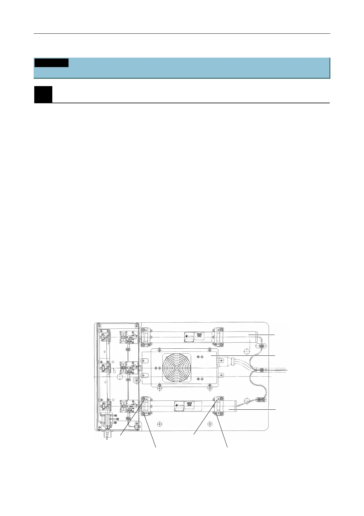
Without touching the coupler, adjust only the laser body to transmit the laser beam through the
optical-fiber cable. (Figure 5.2-29)
Incident light efficiency of more than 50% should be achieved at the emitting end of the optical-fiber
cable relative to values measured in front of the coupler.
1. Close the shutters for the argon and He-Ne2 lasers so that only the He-Ne1 laser beam enters the
optical-fiber cable.
2. Mount the end of the optical-fiber cable onto the power meter tool and measure the light intensity
with the power meter.
3. Adjust the front and rear setscrews on either the right or the left side of the laser. (Front setscrew
R1 and rear setscrew R2 on the right side are adjusted by the following example.)
(1) Rotate the front setscrew R1 (close to the laser-emitting end) 30 to 60 degrees in either
direction.
(2) Rotate the rear setscrew R2 (on the same side as the setscrew rotated in step (1)), located
on the back of the laser, in the same direction as in step (1). Adjust the laser body position at
which the power meter indicates a greater light intensity.
(3) If light intensity does not increase, rotate the setscrews R1 and R2 (in that order) in the
opposite direction of the rotation in step (1). Adjust the laser body position at which light
intensity becomes greater.
(4) Repeat steps (2) and (3) to adjust the position at which light intensity is greatest.
4. Adjust the front and rear setscrews on the other side of the laser and locate the laser body position
at which light intensity is greatest. (Front setscrew L1 and rear setscrew L2 on the left side, in this
example.)
5. When setscrews R1 and R2 are adjusted again, the light intensity may be further increased.
6. Record the light intensity.
Figure 5.2-29
He-Ne2
He-Ne1
Rotate screw R1 first.
Note the rotating direction
and turning angle.
Rotate R2 after R1 and in
the same direction as R1
Setscrew L1
Setscrew L2

 Loading...