Chapter 5 Laser Unit
5.3 C-LU3EX Three-laser Unit EX
1-146
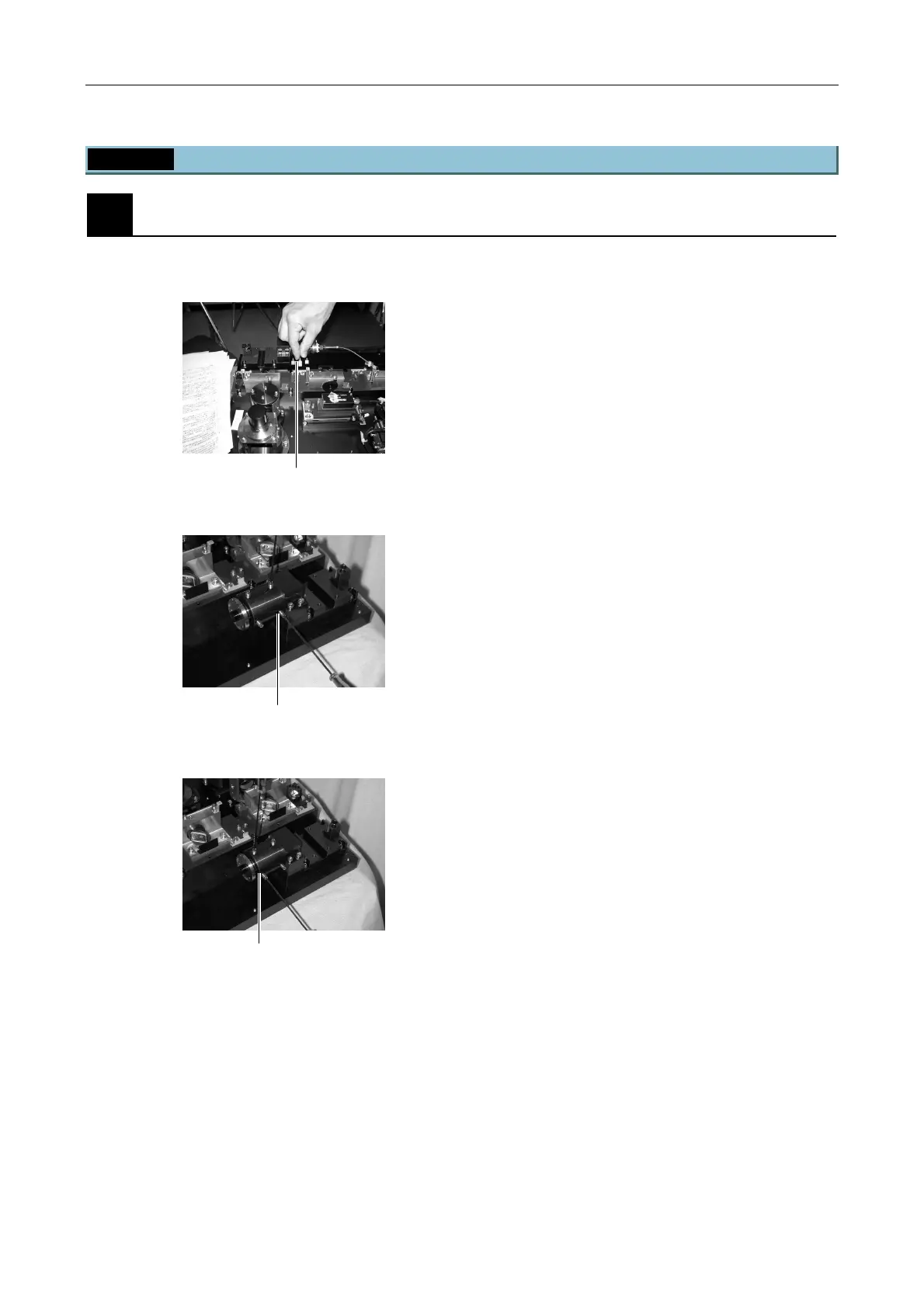
5.3.5 Final Adjustment for the Ar Laser Light with the Optical Fiber
1
Centering the Ar laser
The Ar laser beam is aligned with the coupler centering tool pinhole.
Figure 5.3-56
1. Loosen the clamp screw on the coupler unit.
Figure 5.3-57
2. Set the coupler centering tool pinhole in the laser
incident direction, place a card on the emission side,
and adjust the H and V laser incidence side
adjustment screws to find the point giving maximum
brightness.
Figure 5.3-58
3. Set the coupler centering tool pinhole in the direction
of laser emission and adjust the H and V fiber side
adjustment screws to find the point giving maximum
brightness.
4. Repeat steps 2. and 3. two or three times to find the
point of maximum brightness.
Laser incidence side adjustment screw
Fiber side adjustment screw
Clamp screw (center)

 Loading...