Chapter 5 Laser Unit
5.1 Overview of the Laser Units
2-45
5.1 Overview of the Laser Units
5.1.1 LU4A Four-laser Module A (with LU4-B5 Beamsplitter 50/50 installed)
This laser unit is mounted with four kinds of lasers (with one laser product per color) selected from the lasers
listed in Table 8.1-2 Recommended lasers. To adjust laser intensity, control the AOTF with the operation
software. Each laser on this unit is equipped with a motorized shutter controllable by the TI-LU4SU shutter
unit LU4 or the software. Each laser beam is halved by the built-in Beamsplitter 50/50 (LU4-B5) and the
resultant beams are led into the TIRF-PAU illuminator through the two single-mode optical fibers. A motorized
shutter is provided between the Beamsplitter 50/50 and each of the single-mode optical fiber outlets. To
control these shutters, select optical path by the Shutter unit LU4 or the software.
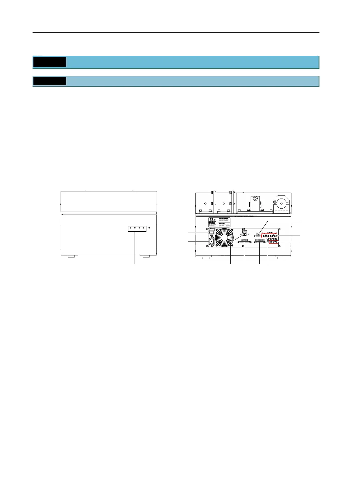
Each one of the four orange LEDs on the front of the unit lights up to indicate that the motorized shutter for the
corresponding laser is ready to be opened for laser emission. When the motorized shutter is closed, the
corresponding LED does not light up.
L4
L3
L2
L1
POWER
Figure 5.1-1
Figure 5.1-2
(1) Power switch
This is the main power switch of this unit.
When this switch is pressed, power is supplied to the primary source only. Power supply to the
secondary source is subject to the state of the remote switch (3).
(2) AC inlet
(3) Remote switch
This is the remote power switch of this unit.
When this switch is on, power is supplied to the secondary source in conjunction with the power supply
to the PC.
When this switch is off, power is supplied to the secondary source when the power switch (1) is pressed,
independently of the power supply to the PC.
(4) CONTROLLER connector
This connector is for future extension. (Do not use in this system.)
(5) AOTF/PC connector
This connector is for future extension. (Do not use in this system.)
Indicating shutter conditions
(1)
(3)
(9)
(6)
(5) (4) (8)
(2)
(7)

 Loading...