Chapter 5 Laser Unit
5.4 LU4A Four-laser Module A
1-171
5.4.3 Laser Rough Adjustment 1
1
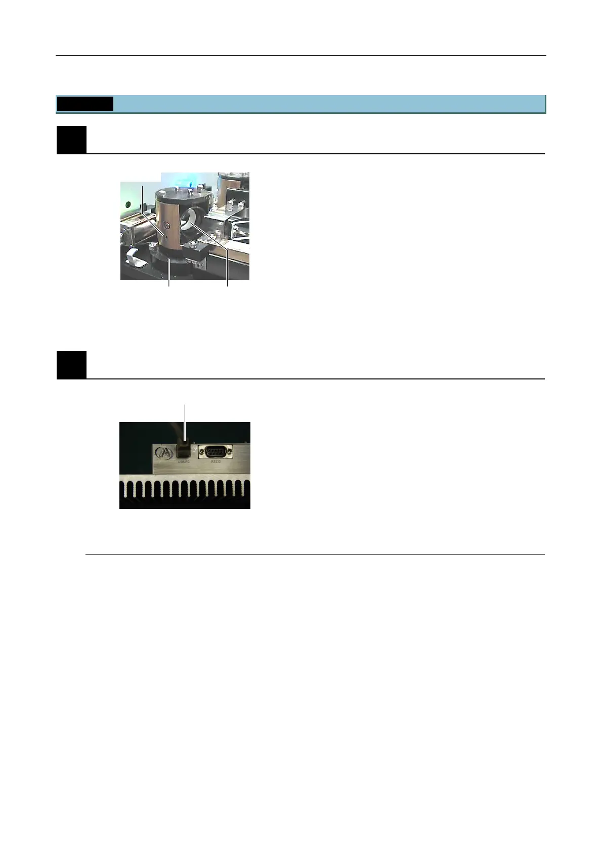
Checking the initial beam shift unit position
Figure 5.4-40
1. The tool hole and the horizontal clamp screw on the
side of the beam shift part must be aligned vertically.
2. The cylindrical glass must not tilt significantly.
* Check all beam shift parts in steps 1 and 2. (By
default, the beam shift parts are arranged as
described above.)
2
Connect the AOTF driver remote controller.
Figure 5.4-41
Connect the cable of the AOTF driver remote
controller to the USB connector of the AOTF driver at
the lower part of the laser unit.
AOTF driver remote controller
Connect the AOTF remote controller cable to the USB port of the AOTF driver. When connected,
the remote controller screen displays “external mode.”
To change the screen on the controller to internal mode, press any numeric key on the controller.
Then, press the numeric key assigned to the required laser wavelength (see the table below for
the key assignment list). The wavelength number will be displayed on the screen and the
corresponding laser beam starts irradiating. To cancel the selection, press the key again. The
frequency and the power level can be set for individual laser wavelength.
Tool hole
Cylindrical glassHorizontal axis clamp screw
AOTF driver USB connector

 Loading...