Chapter 1 System Configurations and Part Names
1.2 Optical Paths of Lasers
2-5
1.2 Optical Paths of Lasers
1.2.1 Laser Unit
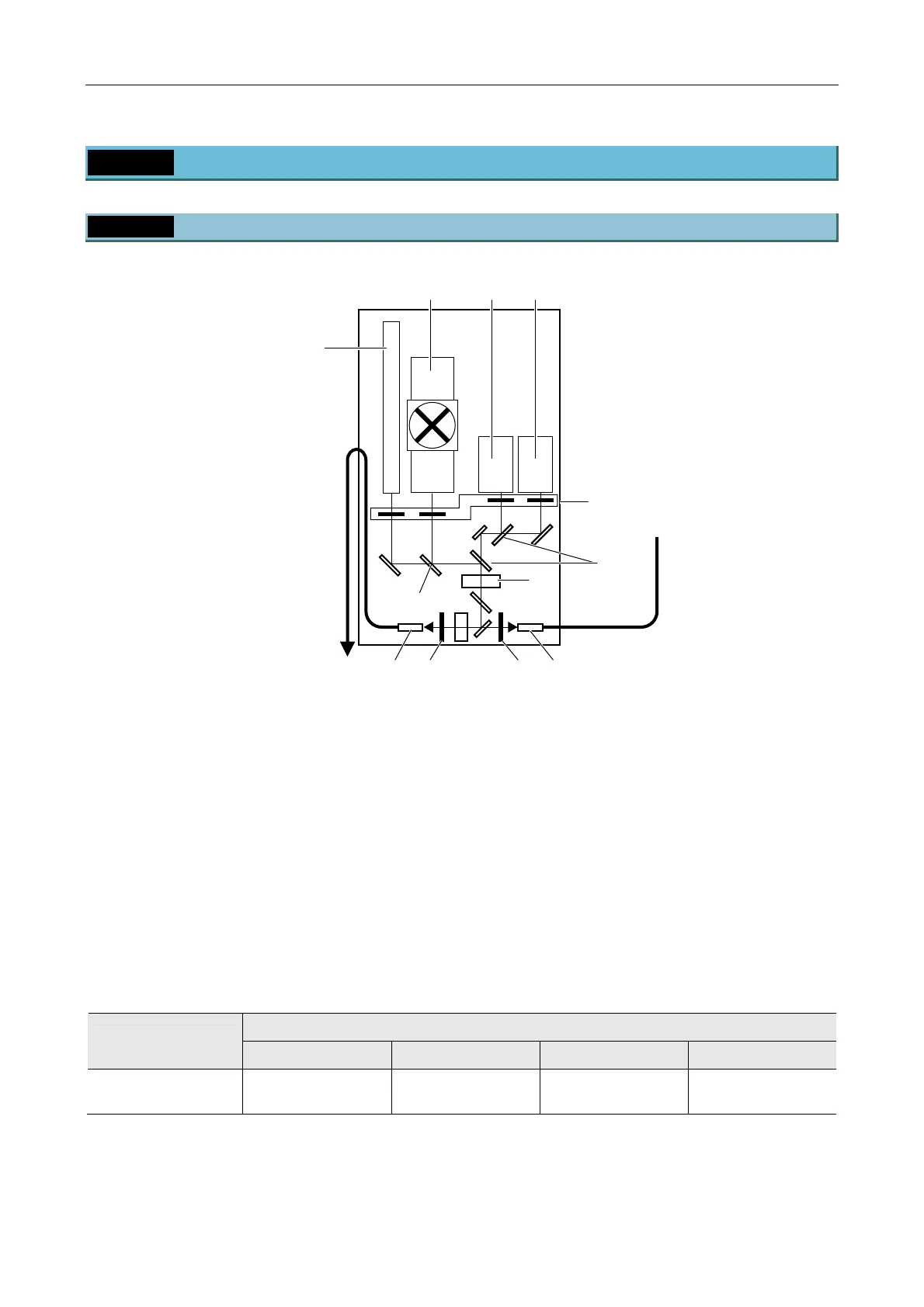
Figure 1.2-1
(1) Laser mounting position L1
(See the table below.)
(2) Laser mounting position L2
(See the table below.)
(3) Laser mounting position L3
(See the table below.)
(4) Laser mounting position L4
(See the table below.)
(5) Motorized shutters
(6) Laser coupling mirror
(7) Laser outlet (single-mode optical fiber)
(8) AOTF brightness adjustment part
Table 1.2-1
Laser mounting position
Model name
L1 L2 L3 L4
LU4A
four-laser module A
630 nm to 650 nm 400 nm to 445 nm 455 nm to 515 nm 540 nm to 595 nm
LU4A four-laser module A
(with LU4-B5 Beamsplitter 50/50 installed)
(3)
(5)
(4)
(6)
(8)
(2) (1)
(6)
(7) (5) (5) (7)

 Loading...