Chapter 6 Connection between the Laser Unit and the Microscope
6.3 Replacement of Optical Path Switch Mirror
2-62
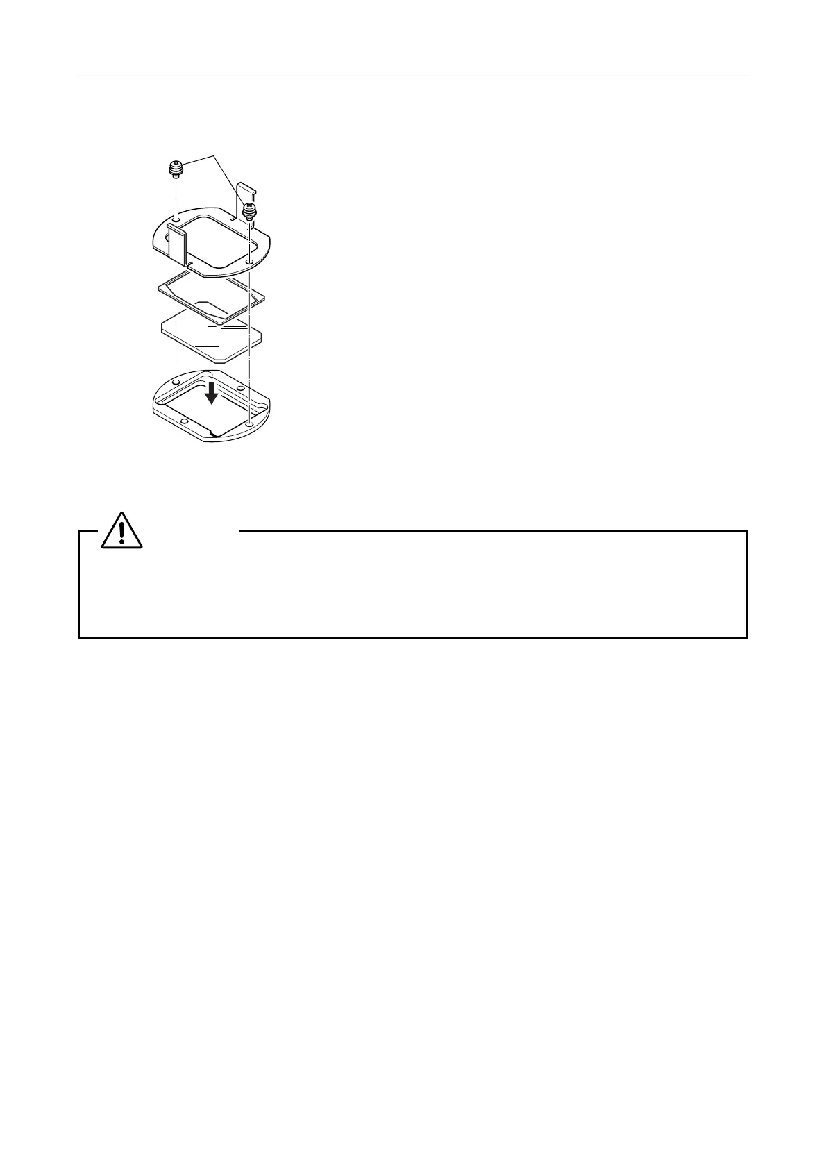
4. Remove the two holder plate locking screws. And then,
remove the holder plate and flat spring to replace the
mirrors.
Mirror size: 36 x 25.7 x 1
Figure 6.3-4
5. Assembly is the reverse of disassembly.
Place the reflection surface of the mirror downward into
the cutout of the mirror frame.
There is a positioning hole on the mirror unit. Securely
attach the mirror unit to the illumination attachment to fit
the pin on the main body.
CAUTION
To using the laser beam for passing through the mirror, if the mirror is not set in a collimated angle,
interference fringes may appear in the PA-GFP illumination. Carefully set the mirror in a collimated
angle except when using a total reflection mirror.
(Standard collimated angle for the half mirror is 5".)
Holder plate locking screws
Holder plate
Flat spring
Mirror
(Place the
reflection
surface
downward.)

 Loading...