Electrical System 108Service Manual – CS7000
Component Locations
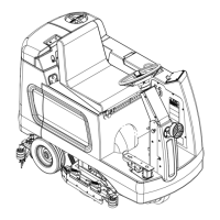
• 36 volt Battery (Battery Model)
• 36 volt Battery Pack (Hybrid Models) - Right of engine under fuel tank.
• 42 volt Generator - Front of engine behind rubber shield. (Raise hopper for access.)
• Circuit Breaker Panel
• Starting Battery
• Electrical Panel - Left side of solution tank under metal plate. (Remove recovery tank for access.)
• Main Fuse F1 400 Amps
• F2 150 Amp Fuse
• Auxiliary Relay - See Electrical Panel
• Auxiliary Contactor - See electrical panel
• Horn
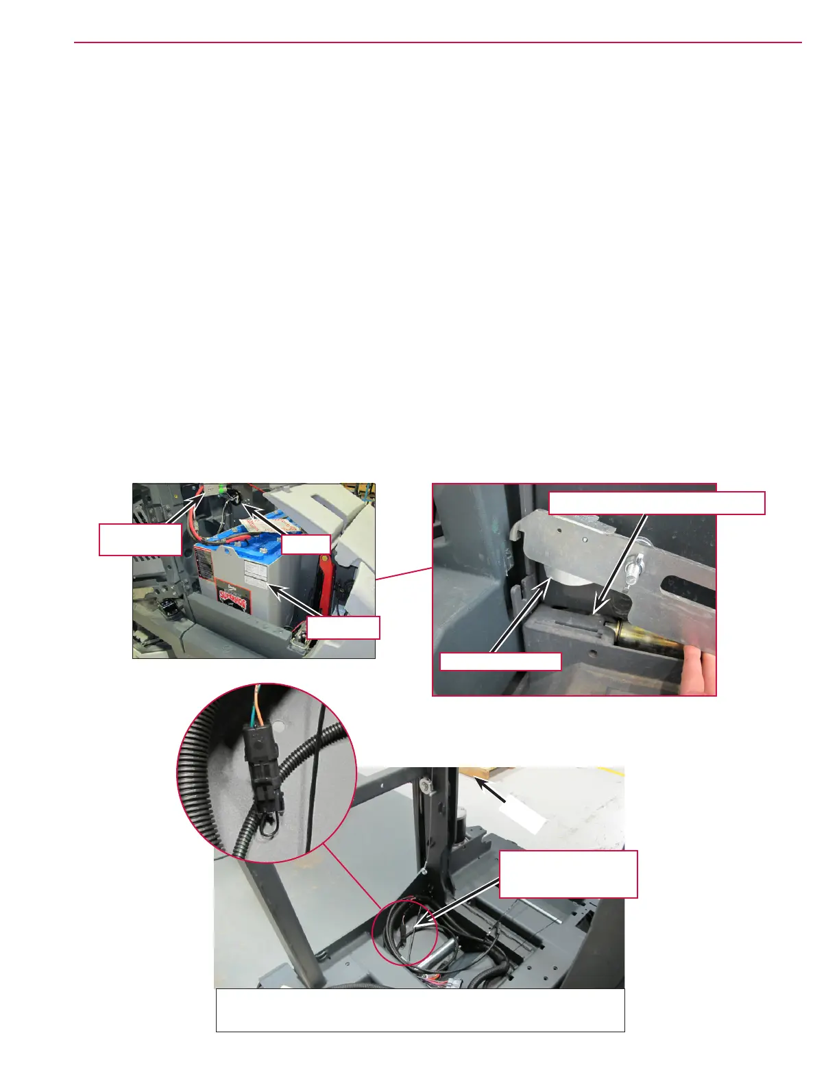
• Battery Interlock Switch (Hybrid models use a jumper in place of this switch)
• Seat Switch
Battery Interlock Switch - Under here
Switch “reads” tang
36 volt Battery (Battery Model)
Main Power
Disconnect
Horn
36v Battery
Engine Compartment area. Shown during assembly for clarity.
Battery Interlock
Connector with Jumper
on Hybrid Model
Front

 Loading...