Hopper System 254Service Manual – CS7000
The Following Conditions Must Be Met for the Hopper Door Open and Close
• There must be positive voltage to the J7-1 Interlock Input. For this to happen:
– The Seat Switch S9 must be closed.
– The Safety Relay K14 on the Steer By Wire Controller A5 must energize the coil to close the Safety Relay
K14
contactor.
– The Emergency Stop Switch S15 must be closed.
– The Battery Interlock S13 must be closed (battery machines) or jumpered (Diesel and LPG machines).
• The J3-6 and J3-7 Outputs must provide voltage to the Dump Door Actuator Motor M26 when the A1 Main
Machine Controller
receives a signal from the A3 Control Panel via the CAN BUS that the operator has
pressed the hopper door open or hopper door close button.
– For the hopper door to open, the A1 Main Machine Controller must not receive negative voltage at the J7-
22
Input from the Dump Door Extend Limit Switch S7.
– For the hopper door to close, the A1 Main Machine Controller must not receive negative voltage at the J7-
23
input from the Dump Door Retract Limit Switch S8.
Component Locations
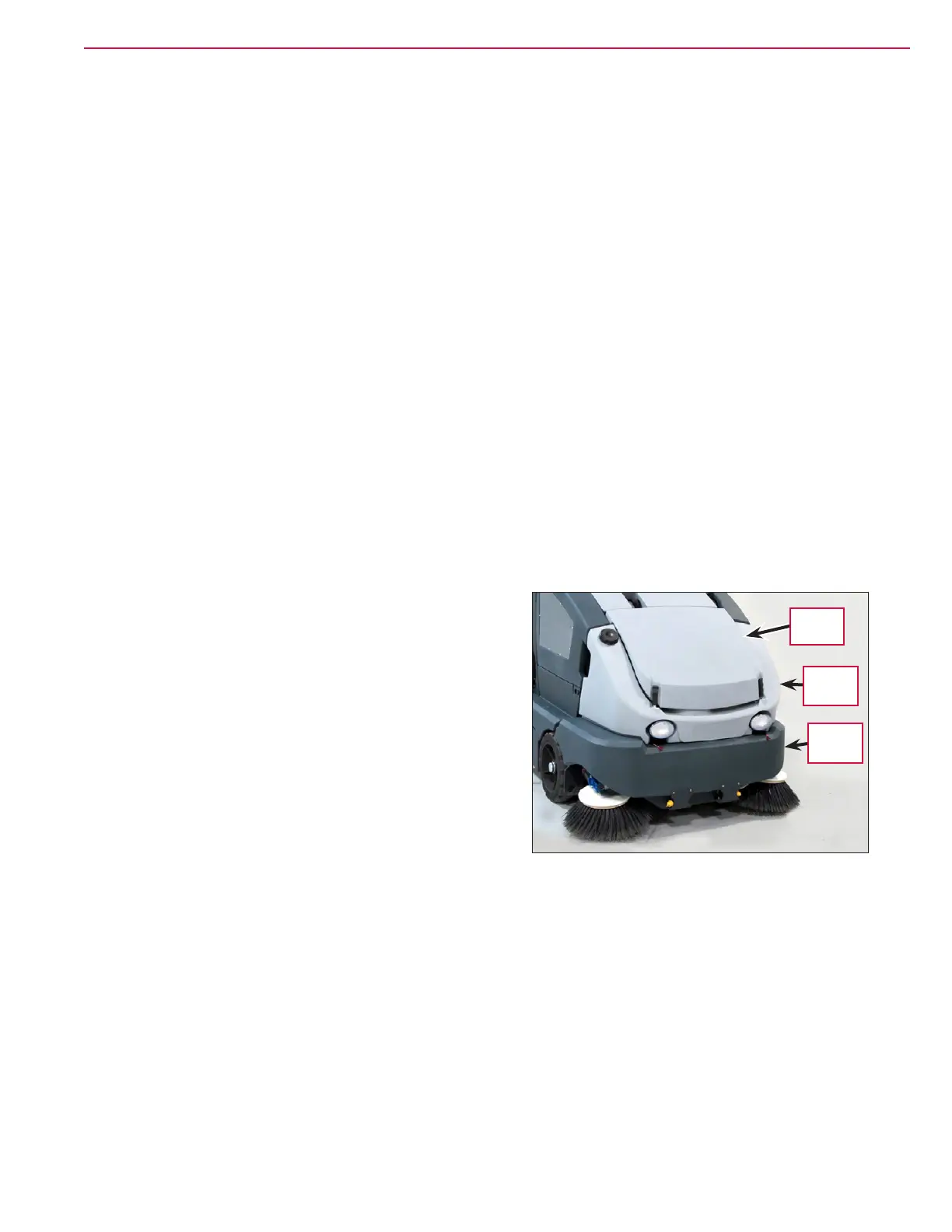
Upper and Lower Hopper
The Upper Hopper (light gray) and Lower Hopper (dark
gray) are on the front of the machine, The Hopper Cover
houses the dust control impeller pump, lter and lter
shaker assembly. The Upper and Lower Hoppers are
connected and pivot up and down as a single unit.
Hopper
Cover
Upper
Hopper
Lower
Hopper

 Loading...