Wheel System, Traction 434Service Manual – CS7000
Specications
Shop Measurements
Shop measurements are values that were measured on a real machine. While they are not “specications”,
they can help you recognize normal vs abnormal.
Drive Controller Voltage Measurements
All voltages are DC unless otherwise stated and were measured with the negative (black) voltmeter lead on
battery negative and the key switch on.
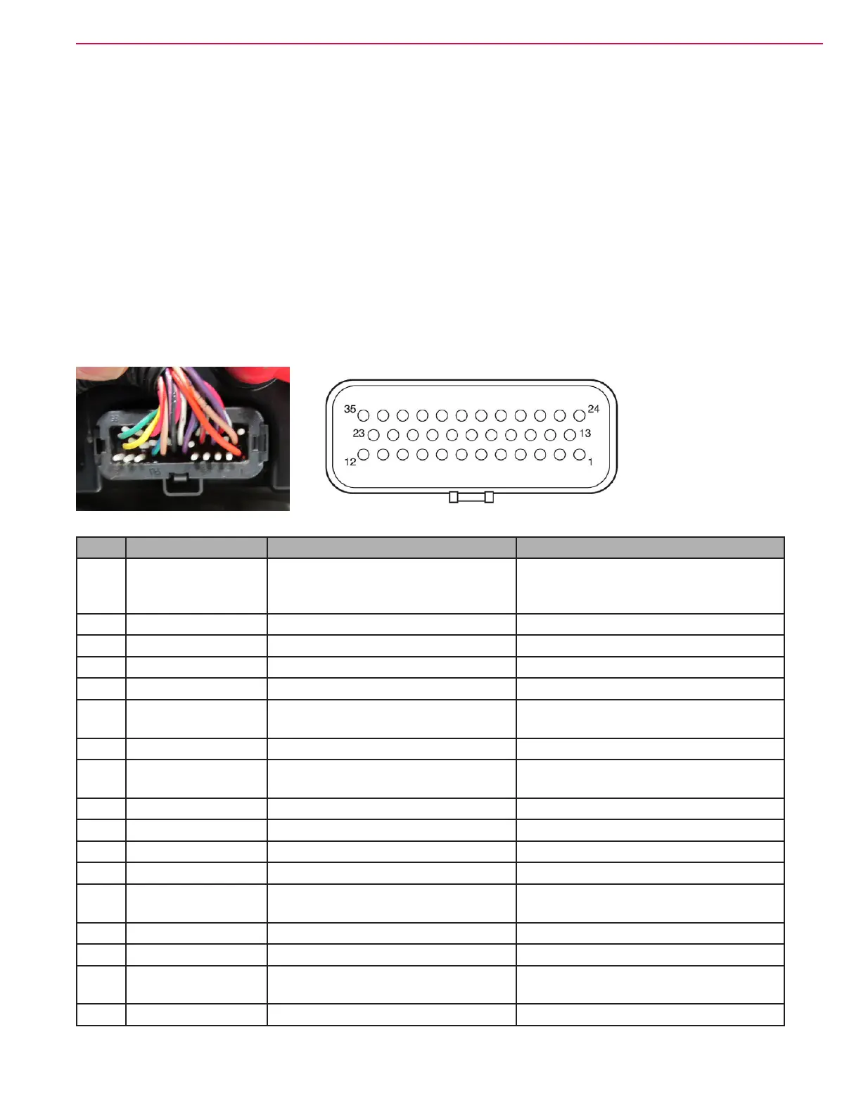
Low Current 35 Pin Connector (J4)
Pin Wire Color Circuit Voltage
1 ORN Key switch input. Provides logic
power for the controller and power
for the coil drivers.
38.12 V
2 Not Used
3 Not Used
4 Not Used
5 Not Used
6 VIO/GRN K7 Wheel Drive Contactor Driver Momentary 38 V at rst key on. 5-6v
when contactor is “on”
7 BLK/PINK Input and output ground reference. 0.008 V
8 TAN/RED Motor Temperature Sensor 1.22 V (Room Temp) 12 V (open
circuit)
9 GRN/BLU Interlock Switch Input 38.8 V
10 Not Used
11 Not Used
12 Not Used
13 TAN/RED K7 Wheel Drive Contactor Coil
Power
38.18 V
14 Not Used
15 WHT/BLK Throttle POT High (5 V supply) 5.14 V
16 BRN/RED Throttle POT wiper (Pedal Position
Sensor Input)
4.79 V Full Forward 2.52 V Neutral
0.29 V Full Reverse
17 Not Used

 Loading...