Wheel System, Traction 435Service Manual – CS7000
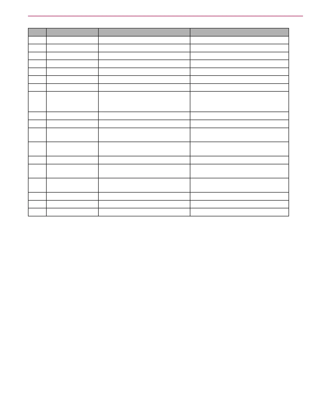
Pin Wire Color Circuit Voltage
18 VIO/BLK Throttle POT Low 0.21 V
19 Not Used
20 Not Used
21 Not Used
22 Not Used
23 YEL CAN Bus High 2.53 V
24 Not Used
25 VIO/WHT Unregulated low power +12 V
output. (Power for Serial Port
Connector)
12.91 V
26 PINK/RED Regulated low power +5v output 4.90 V
27 Not Used
28 WHT/ORN Serial Transmit for Serial Port
Connector
0.18 V
29 BLU/GRN Serial Receive for Serial Port
Connector
0.29 V
30 Not Used
31 PINK/WHT Drive Motor Encoder (Speed
Sensor) Signal - Phase A
4.06 V or 0.08 V stationary 2.0 V wheel
spinning any speed
32 PINK/BLU Drive Motor Encoder (Speed
Sensor) Signal - Phase B
4.06 V or 0.08 V stationary 2.0 V wheel
spinning any speed
33 Not Used
34 Not Used
35 GRN CAN Bus Low 2.45 V
Motor U, V and W Terminal Pair Voltages
• U to V - 0.3 - 2.2 VAC with stationary motor. Up to 26 VAC with wheel off ground and full forward speed.
• V to W - 0.3 - 2.2 VAC with stationary motor. Up to 26 VAC with wheel off ground and full forward speed.
• W to U - 0.3 - 2.2 VAC with stationary motor. Up to 26 VAC with wheel off ground and full forward speed.
Motor U, V and W Terminal Pair Frequency
• U to V -21-23 KHZ with stationary motor. Up to 300 KHZ with wheel off ground and full forward speed.
• V to W -21-23 KHZ with stationary motor. Up to 300 KHZ with wheel off ground and full forward speed.
• W to U -21-23 KHZ with stationary motor. Up to 300 KHZ with wheel off ground and full forward speed.

 Loading...