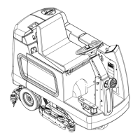
Squeegee System 345Service Manual – CS7000
Circuit Description
The following conditions must be met for the squeegee system to operate:
• The Hopper Interlock Switch S3 must be closed.
• There must be positive voltage to the J7-1 Interlock Input. For this to happen:
– The Seat Switch S9 must be closed.
– The Safety Relay K14 on the Steer By Wire Controller A5 must energize the coil to close the Safety Relay
K14
contactor.
– The Emergency Stop Switch S15 must be closed.
– The Battery Interlock S13 must be closed.
• The A1 Main Machine Controller must receive a signal from the A3 Control Panel via the CAN BUS that the
operator has pressed the scrub switch.
• The J2-8 and J2-9 Outputs from the A1 Main Machine Controller provide voltage to the Squeegee Actuator
Motor M12
. The output polarity determines whether the Squeegee Actuator Motor lowers or raises the
squeegee.
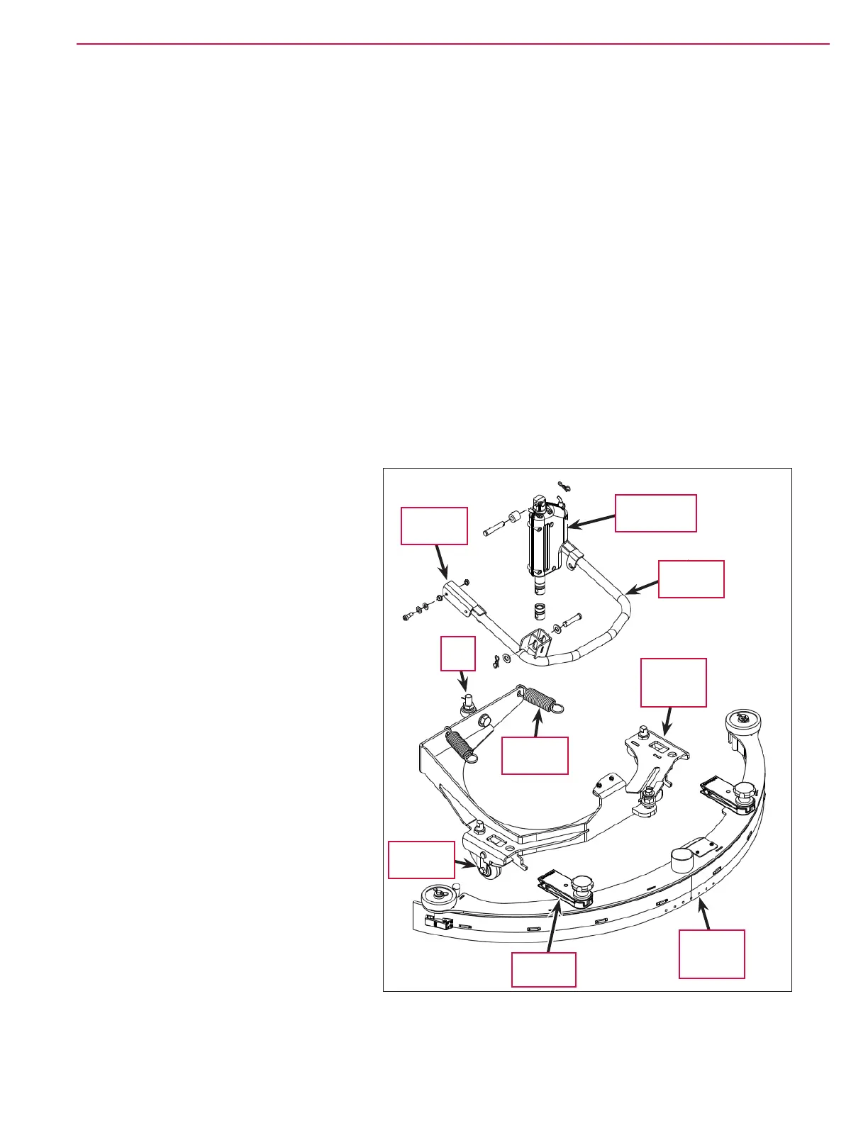
Component Locations
The Rear Squeegee Assembly is attached
to the Squeegee Support Assembly with
two split Squeegee Clips that clamp onto
horizontal pins in the Squeegee Support
Assembly
.
The front of the Squeegee Support Assembly
is attached to the machine frame by a
pivoting Rod End. This allows the rear
of the Squeegee Support Assembly and
attached squeegee to tilt up and down, and
pivot side-to-side to conform to the oor
surface. The two Squeegee Casters support
the Squeegee Support Assembly on the oor.
The rear of the Squeegee Support Assembly
rests on and is supported by the Squeegee
Lift Arm
. The pivoting Front Brackets on
the Squeegee Lift Arm are attached to the
machine frame. The Squeegee Lift Actuator
raises and lowers the rear of the Squeegee
Lift Arm
, which pivots up and down to raise
and lower the Squeegee Support Assembly
and the attached Rear Squeegee Assembly.
The Squeegee Support Assembly and Rear
Squeegee Assembly
swing left-to-right to
allow the Rear Squeegee Assembly to pick
up water on the inside of the corner when
machine is turning. The Extension Springs
re-center the Squeegee Support Assembly
and Rear Squeegee Assembly once the
machine is again moving in a straight line.
Rear
Squeegee
Assembly
Squeegee Lift
Actuator
Squeegee
Lift Arm
Squeegee
Clip (2)
Squeegee
Support
Assembly
Rod
End
Front
Bracket (2)
Squeegee
Caster (2)
Extension
Spring (2)

 Loading...