Wheel System, Traction 410Service Manual – CS7000
Powering up the Drive Controller
When the key switch is turned on, power is supplied on the orange wire to pin J4-1. When each interlock
switch closes (seat switch, safety relay switch, emergency stop switch and battery interlock switch ), power
is supplied on the green/blue wire to pin J4-9. When power is available on both J4-1 and J4-9, the drive
controller supplies battery voltage out of J4-13 to the K7 wheel drive contactor. The power ows through
the contactor coil and back into the controller at J4-6 where it is switched to ground to energize the K7
wheel drive relay. The contacts of the energized K7 contactor supply battery power to the large B+ bolt-on
terminal of the controller. Ground (Battery Negative) is supplied to the large bolt-on B- terminal of the drive
controller.
Drive Pedal Sensor
The primary sensor input is the drive pedal sensor. The drive controller supplies 5 volts out of pin J4-15
on the white/black wire to the drive pedal sensor. The voltage passes through the potentiometer resistive
strip and returns to the drive controller on the violet/black wire to pin J4-18 where it is grounded inside
the controller. The drive pedal sensor input (wiper) goes from the sensor on the brown/red wire to pin J4-
16. When the drive pedal is in the spring loaded neutral position, the wiper is exactly in the middle of the
resistive strip. This provides an input equal to 1/2 of the voltage available across the resistive strip - 2.5v.
When the drive pedal moves forward, the wiper moves closer to the 5v supply increasing the input voltage.
When the drive pedal moves backward, the wiper moves closer to the ground supply decreasing the input
voltage.
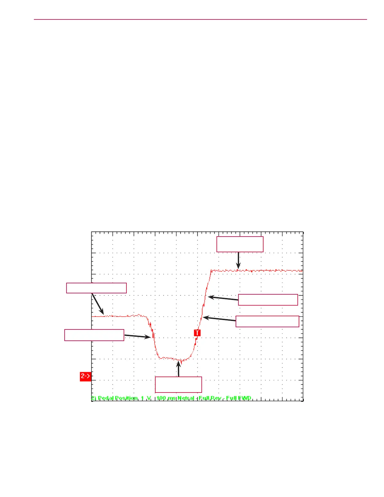
Below is an oscilloscope waveform that shows the drive pedal sensor “sweep” starting in the neutral position,
moving to full reverse then to full forward.
WaveStar : NotesSheet(10) Page: 1
Drive Pedal Sensor Input “sweep”
Moving Backward
Neutral Position ~2.5v
Full Reverse
Position ~0.3v
Return to Neutral ~2.5v
Full Forward
Position ~4.7v
Moving Forward

 Loading...