Wheel System, Traction 413Service Manual – CS7000
CAN Bus
The drive controller communicates with the main machine controller via the CAN Bus. The drive controller
transmits error codes to the main machine controller. The main machine controller sends several messages
to the drive controller that regulate machine speed mode.
The drive controller has three speed setting modes.
1. Transport - This is set at 100% of the total speed potential.
2. Scrubbing Speed - (Battery models only) This is set at 80% of the total speed potential. The user can
override the scrubbing mode by pressing the speed switch.
3. Hopper Up - This is set at 50% of the total speed potential for safety reasons.
The following table explains what conditions dictate the speed mode which is used.
Condition Battery Model - Speed Mode Hybrid Models - Speed Mode
Hopper Up Hopper Up Hopper Up
Hopper Down, Not Scrubbing Transport Transport
Hopper Down, Scrubbing, No
Override
Scrubbing Transport
Hopper Down, Scrubbing,
Override
Transport Transport
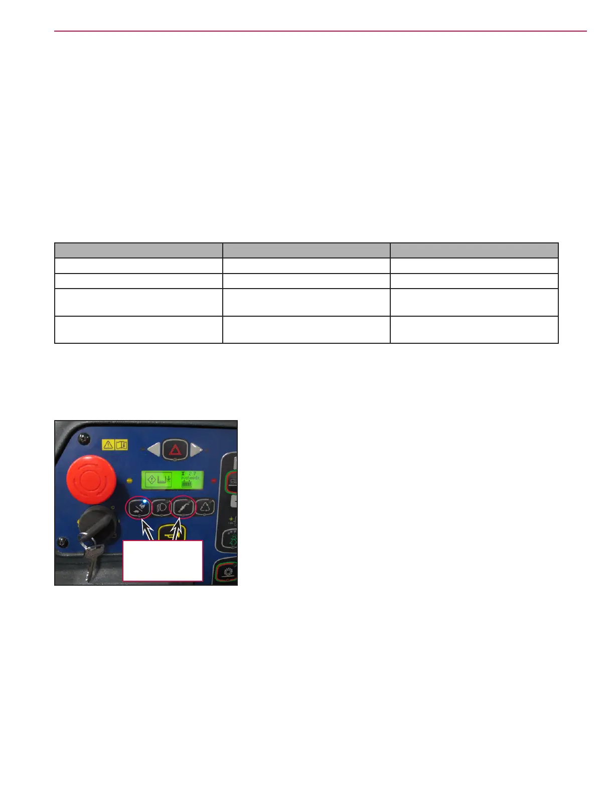
The main machine controller also communicates a special “Push Mode” request to the drive controller via
the CAN Bus, when initiated by the user. Normally the drive motor “locks” the drive wheel to prevent it
from rotating when in the neutral position. The push mode allows the drive wheel to turn without resistance
while still allowing steering operation making it easier to tow the machine. To request the push mode, turn
the key switch on while pressing and holding both the speed switch and the high pressure wand switch.
Press and hold
while turning key
switch on to enter
Push Mode
Hand Held Programmer
The drive controller can communicate with a hand held “programmer”. The controller provides power for
the programmer by sending 12v out of pin J4-25 to the serial port connection pin 4. The transmit wire runs
between controller pin J4-28 and serial port connection pin 3. The receive wire runs between controller pin
J4-29 and serial port connection pin 1. The serial port pin 2 provides a ground for the programmer.

 Loading...