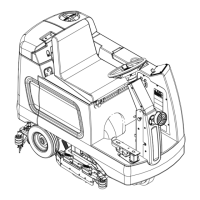
Sweep System, Side Broom 403Service Manual – CS7000
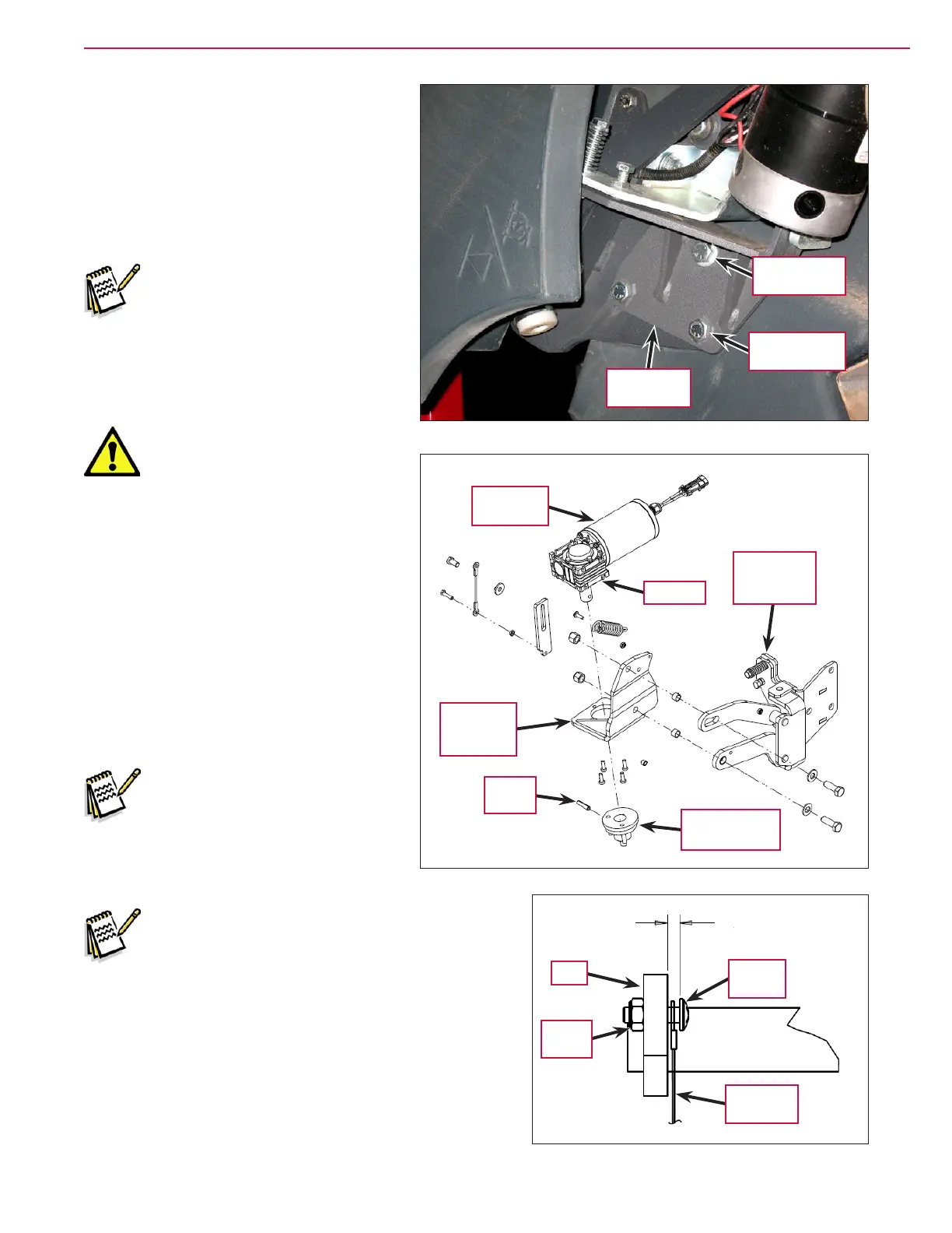
10. Slightly loosen the 1/2”-13 x .75”
Hex Screw
. Note that this screw is
threaded directly into the hopper lift
weldment.
11. Remove the two 1/2”-13 x 1.5” Hex
Screws
, washers and Nyloc
®
nuts.
Note that the washers and Nyloc
®
nuts are located inside the hopper.
Note: Removing the Side Broom
Assembly
is easier if one
person holds the Side
Broom Assembly
in place
while another person
removes the 1/2”-13 x .75”
Hex Screw
.
Caution: Handle the Side
Broom Assembly carefully
as you remove it from the
machine. The Motor Bracket
Weldment and attached Motor
Assembly are free to move on
the Side Broom Arm Assembly
and can create pinch points.
12. Remove the 1/2”-13 x .75” Hex Screw
and washer and carefully remove
the Side Broom Assembly from the
machine.
13. Reinstall the side broom motor
assembly by following the above steps
in reverse order.
Service Note: Use Loctite
®
#242
(blue) on the 1/2”-13 x .75” Hex
Screw
when you reinstall the
Screw.
Service Note: When you reinstall the Cable
Assembly
to the Arm on the side broom lift
weldment, leave a 0.19” ± 0.03” [4,8 mm ± 0,7
mm] gap between the Phillips Screw and Arm to
allow the Cable Assembly to move freely on the
Phillips Screw.
1/2”-13 x .75”
Hex Screw
1/2”-13 x 1.5”
Hex Screw (2)
Side Broom
Assembly
Motor
Bracket
Weldment
Motor
Assembly
Side
Broom Arm
Assembly
Side Broom Hub
Assembly
Spring
Pin
Gearbox
0.19” ± 0.03” [4,8
mm ± 0,7 mm]
Phillips
Screw
Cable
Assembly
Nyloc
®
Nut
Arm

 Loading...