5.67
BODY / STEERING / SUSPENSION
5
9924125 - 2013 RANGER RZR / RZR S / RZR 4 Service Manual
© Copyright 2012 Polaris Sales Inc.
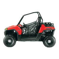
• Note the orientation of the bleed shim tabs as the
assembly would be installed on the shock shaft
(Fig. 19).
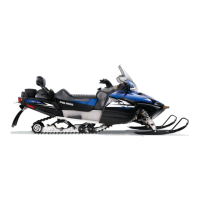
11. Install the piston valve as sho
wn in the photo (Fig 20).
Install the lock nut and torque to specification. Keep
the bleed shim tab aligned with the piston valve when
tightening the lock nut.
12. Install the rebound valve stack onto the shock shaft.
Tighten
the lock nut to specification.
NOTE: Verify the bleed valve shim tab is orientated
c
orrectly with the piston valve when tightening lock
nut.
13. Replace the IFP o-ring. Apply a thin layer of low
teme
rpature grease to the IFP.
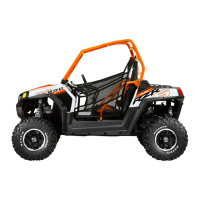
14. Install the IFP into the shock body with the relief
con
tour facing the shock shaft end of the shock (Fig.
21).
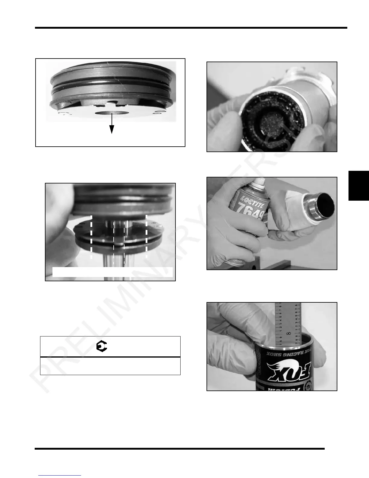
15. Apply Loctite Primer N to the shock body bearing cap
th
reads (Fig. 22).
16. While the primer is curing, set the IFP depth to the
INITAL SETTING spe
cification noted at the beginning
of this chapter (Fig. 23).
17. Handle the shock body with care after setting the IFP
de
pth. Do not move the IFP after initial setting is
established.
Shock Shaft Lock Nut:
22 ft-lbs (30 Nm)
Bleed shim / piston valve installation direction.
Figure 19
Tab centered in middle of compression port.
Figure 20
 Loading...