EasyManua.ls Logo

Rigol DS1000Z Series User Manual

Rigol DS1000Z Series
264 pages
To Next Page IconTo Next Page
To Previous Page IconTo Previous Page
Page #108 background imageLoading...
Page #108 background image
RIGOL Chapter 5 To Trigger the Oscilloscope
DS1000Z Users Guide
5-36
I2C Trigger (Option)
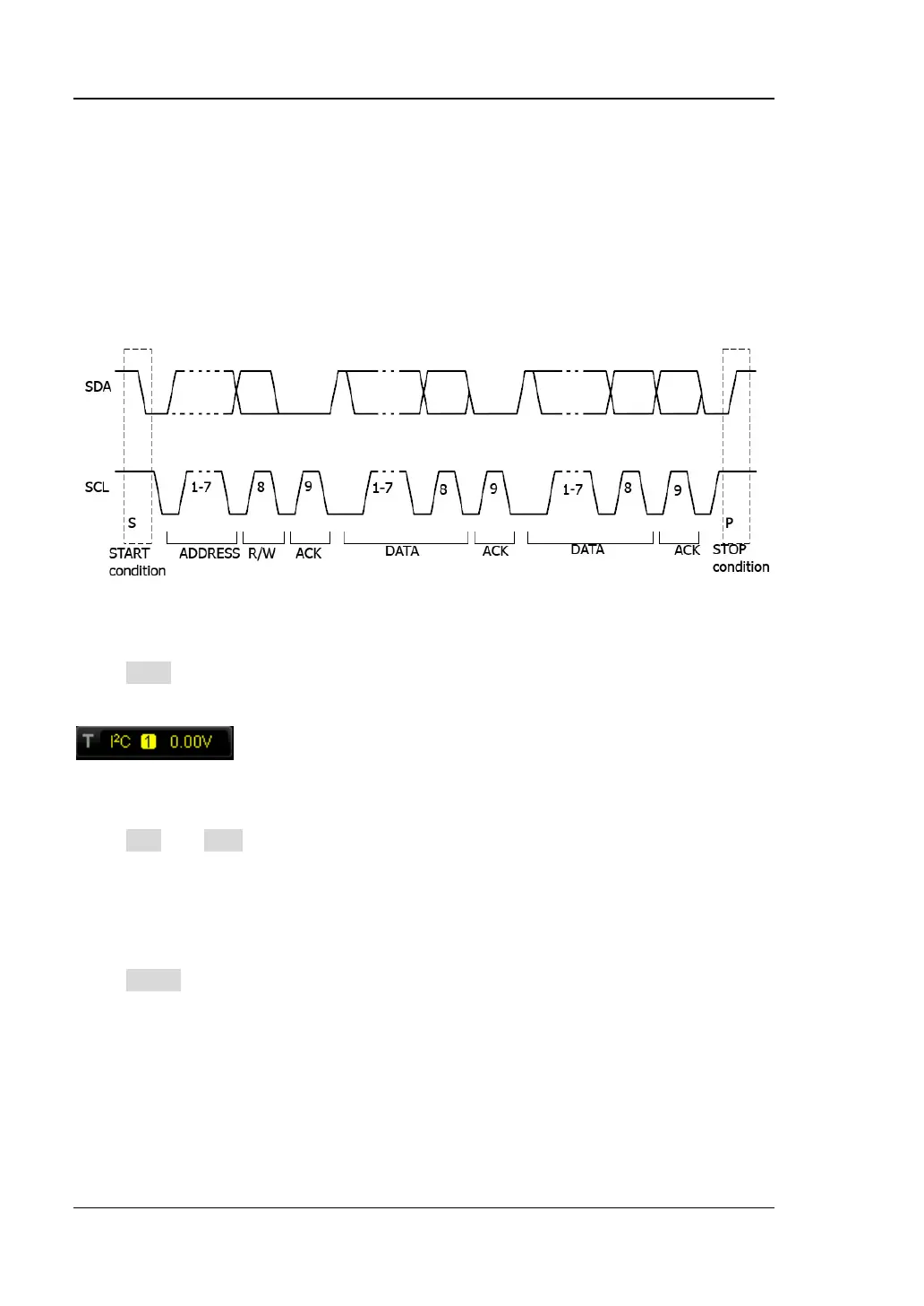
Trigger on the start condition, restart, stop, missing acknowledgement or on the
read/write frame with specific device address and data value. In I2C trigger, you
need to specify the SCL and SDA data sources. The figure below shows the complete
data transmission of I2C bus.
Trigger Type:
Press Type to select I2C. At this point, the trigger setting information as shown in
the figure below is displayed at the upper right corner of the screen.
Source Selection:
Press SCL and SDA to specify the data sources of SCL and SDA respectively. They
can be set to CH1-CH4 and the current trigger source is displayed at the upper right
corner of the screen.
Trigger Condition:
Press When to select the desired trigger condition.
Start: trigger when SDA data transitions from high to low while SCL is high.
Restart: trigger when another start condition occurs before a stop condition.
Stop: trigger when SDA data transitions from low to high while SCL is high.
Missing ACK: trigger when the SDA data is high during any acknowledgement of
SCL clock position.
Address: trigger on the clock (SCL) edge corresponding to the byte of data (SDA)

Table of Contents

Other manuals for Rigol DS1000Z Series

Question and Answer IconNeed help?

Do you have a question about the Rigol DS1000Z Series and is the answer not in the manual?

Rigol DS1000Z Series Specifications

General IconGeneral
Sample Rate1 GSa/s (single channel), 500 MSa/s (dual channel)
Memory Depth12 Mpts (standard), 24 Mpts (optional)
Vertical Sensitivity1 mV/div to 10 V/div
Vertical Resolution8 bits
Timebase Range5 ns/div to 50 s/div
Channels2 or 4
Display7 inch color display
Trigger ModesEdge, Pulse, Video
ConnectivityUSB Host, USB Device, LAN (LXI)
Waveform Capture Rate30, 000 wfms/s
Input Impedance1 MΩ
Power Supply100-240 VAC, 45-440 Hz

Summary

Safety Requirement

General Safety Summary

General safety precautions to avoid personal injury and instrument damage.

Safety Terms and Symbols

Explains warnings, cautions, and symbols used in the manual and on the product.

Measurement Category

Ventilation Requirement

Working Environment

Pollution Degree

General Care and Cleaning

Environmental Considerations

DS1000Z Series Overview

Chapter 1 Quick Start

General Inspection

Inspect shipping container, instrument, and accessories for damage or defects.

Appearance and Dimensions

Provides front and top views of the oscilloscope with dimensions.

Preparing the Oscilloscope for Use

Instructions on adjusting supporting legs and connecting to power.

Connecting the Probe

Guides on connecting passive probes to the oscilloscope's channel connectors.

Function Inspection

Steps to perform a basic function check, including restoring default configuration.

Probe Compensation

Details the procedure for compensating probes to ensure measurement accuracy.

Front Panel Overview

Describes the layout and function of each control on the front panel.

Rear Panel Overview

Describes the connectors and features located on the rear panel of the oscilloscope.

User Interface Overview

Details the oscilloscope's graphical user interface elements and their functions.

Security Lock Usage

Instructions on how to use the security lock to secure the instrument to a fixed location.

Built-in Help System

Explains how to access and navigate the oscilloscope's integrated help system.

Chapter 2 Vertical System Settings

Enabling and Configuring Channels

Guides on enabling and configuring individual input channels (CH1-CH4).

Channel Coupling and Bandwidth Limit

Explains setting coupling modes and enabling bandwidth limiting to filter signals.

Probe Ratio and Waveform Invert

Details setting probe attenuation ratio and inverting waveform display.

Vertical Scale and Expansion

Describes adjusting vertical scale (Volts/Div) and expansion for waveform display.

Amplitude Unit and Channel Label

Explains selecting amplitude units and setting custom labels for channels.

Chapter 3 Horizontal System Settings

Delayed Sweep Function

Explains how to use delayed sweep to enlarge specific waveform sections horizontally.

Time Base Modes (YT, XY, Roll)

Describes different time base modes like YT, XY, and Roll for waveform display.

Chapter 4 Sample System Settings

Acquisition Modes

Explains acquisition modes like Normal, Average, Peak Detect, and High Resolution.

Sample Rate and Waveform Display

Discusses sample rate and its impact on waveform display, including distortion.

Memory Depth Settings

Details memory depth settings and their relation to sample rate and waveform storage.

Chapter 5 Triggering the Oscilloscope

Trigger Basics (Source, Modes, Coupling, Holdoff, Noise Rejection)

Explains trigger source, modes, coupling, holdoff, and noise rejection settings.

Trigger Types (Edge, Pulse, Slope, Video)

Details common trigger types like Edge, Pulse, Slope, and Video triggers.

Advanced Trigger Types (Pattern, Duration, Setup/Hold, Timeout)

Covers advanced trigger types including Pattern, Duration, Setup/Hold, and Timeout.

Serial Protocol Triggers (RS232, I2C, SPI)

Explains triggering for serial protocols like RS232, I2C, and SPI.

Trigger Output Connector

Describes the trigger output connector for signals reflecting capture rate or Pass/Fail test results.

Chapter 6 Making Measurements

Math Operations on Waveforms

Explains various mathematical operations (Add, Subtract, FFT, etc.) on waveforms.

Auto Measurement Features

Details automatic measurement of waveform parameters and quick measurements.

Cursor Measurement Techniques

Describes using cursors (Manual, Track, Auto) for precise X/Y axis measurements.

Chapter 7 Protocol Decoding

Parallel Bus Decoding

Explains how to decode parallel bus signals, including clock and data line settings.

RS232/UART Decoding

Details configuration for RS232 serial bus decoding, including baud rate and packet settings.

I2C Decoding

Describes I2C serial bus decoding settings like clock, data channels, and address information.

SPI Decoding

Explains SPI serial bus decoding settings, including clock, data lines, and modes.

Chapter 8 Reference Waveform

Enabling and Configuring Reference Waveforms

Guides on enabling REF function, selecting sources, and adjusting display.

Saving and Recalling Reference Waveforms

Instructions on saving, resetting, exporting, and importing reference waveforms.

Chapter 9 Pass/Fail Test

Enabling and Configuring Pass/Fail Test

Instructions on enabling, starting, and selecting sources for the Pass/Fail test.

Mask Range and Test Output

Explains defining test masks and setting output modes for test results.

Saving and Loading Test Masks

Instructions on saving and loading test mask files to/from memory.

Chapter 10 Waveform Record

Waveform Recording and Playback

Explains how to start, stop, and play back recorded waveforms.

Playback Settings

Guides on setting playback mode, direction, interval, and frames.

Recording Settings

Details parameters for waveform recording, including interval, length, and beep.

Chapter 11 Display Control

Selecting Display Type and Persistence

Explains setting waveform display mode (Vectors/Dots) and persistence time.

Waveform Intensity and Screen Grid

Details adjusting waveform intensity and screen grid settings.

Grid Brightness and Menu Display

Explains adjusting grid brightness and menu display time.

Chapter 12 Signal Source

Outputting Basic Waveforms

Guides on outputting Sine, Square, Ramp, Pulse, and DC waveforms with parameter settings.

Using Built-in and Arbitrary Waveforms

Lists built-in waveforms and explains creating/editing arbitrary waveforms.

Modulation Functions

Explains AM and FM modulation functions for the signal source.

Chapter 13 Store and Recall

Storage System and Types

Describes storage system, types (Picture, Traces, etc.), and their recall capabilities.

Internal and External Storage

Instructions for saving and recalling data to/from internal and external memory.

Disk Management Operations

Explains file/folder creation, deletion, renaming, and clearing local memory.

Factory Reset

Describes how to restore the oscilloscope to its factory default settings.

Chapter 14 System Function Settings

Remote Interface Configuration (LAN/USB)

Explains how to configure LAN and USB interfaces for remote communication.

System-related Settings (Sound, Language, Recall)

Covers system settings like sound, language, system info, and power-on recall.

Self-calibration and Option Management

Guides on performing self-calibration and managing optional features using serial numbers.

Chapter 15 Remote Control

Remote Control via USB

Details connecting and setting up the oscilloscope for remote control via USB.

Remote Control via LAN

Explains configuring network parameters and establishing remote control via LAN.

Chapter 16 Troubleshooting

Common Screen and Waveform Display Issues

Addresses problems like dark screen, no waveform, unstable display, or incorrect amplitude.

USB Connectivity and Recognition Troubleshooting

Troubleshooting for PC connection failures and USB disk recognition problems.

Chapter 17 Specifications

Sample and Input Specifications

Details specifications for sampling, input coupling, impedance, and probe attenuation.

Horizontal and Vertical Specifications

Provides specifications for time base, bandwidth, resolution, and scale settings.

Trigger and Measurement Specifications

Lists trigger parameters, modes, and specifications for measurement functions.

Math, Display, and Signal Source Specifications

Details specifications for math operations, display features, and signal source capabilities.

General Specifications

Covers probe compensation, power, environment, mechanical, and regulation standards.

Chapter 18 Appendix

Accessories and Options

Lists available models, standard accessories, and optional items for the oscilloscope.

Warranty Information

Outlines RIGOL's product warranty terms and conditions.

Document Feedback

Provides contact information for questions or comments regarding the document.

Related product manuals