Chapter 2 To Set the Vertical System RIGOL
DS1000Z User’s Guide
Channel Coupling
Set the coupling mode to filter out the undesired signals. For example, the signal
under test is a square waveform with DC offset.
When the coupling mode is “DC”: the DC and AC components of the signal under
test can both pass the channel.
When the coupling mode is “AC”: the DC components of the signal under test
are blocked.
When the coupling mode is “GND”: the DC and AC components of the signal
under test are both blocked.
Press CH1 Coupling and use to select the desired coupling mode (the
default is DC). The current coupling mode is displayed in the channel label at the
bottom of the screen. You can also press Coupling continuously to switch the
coupling mode.
Bandwidth Limit
Set the bandwidth limit to reduce display noise. For example, the signal under test is
a pulse with high frequency oscillation.
When bandwidth limit is disabled, the high frequency components of the signal
under test can pass the channel.
Enable bandwidth limit and limit the bandwidth to 20 MHz, the high frequency
components that exceed 20 MHz are attenuated.
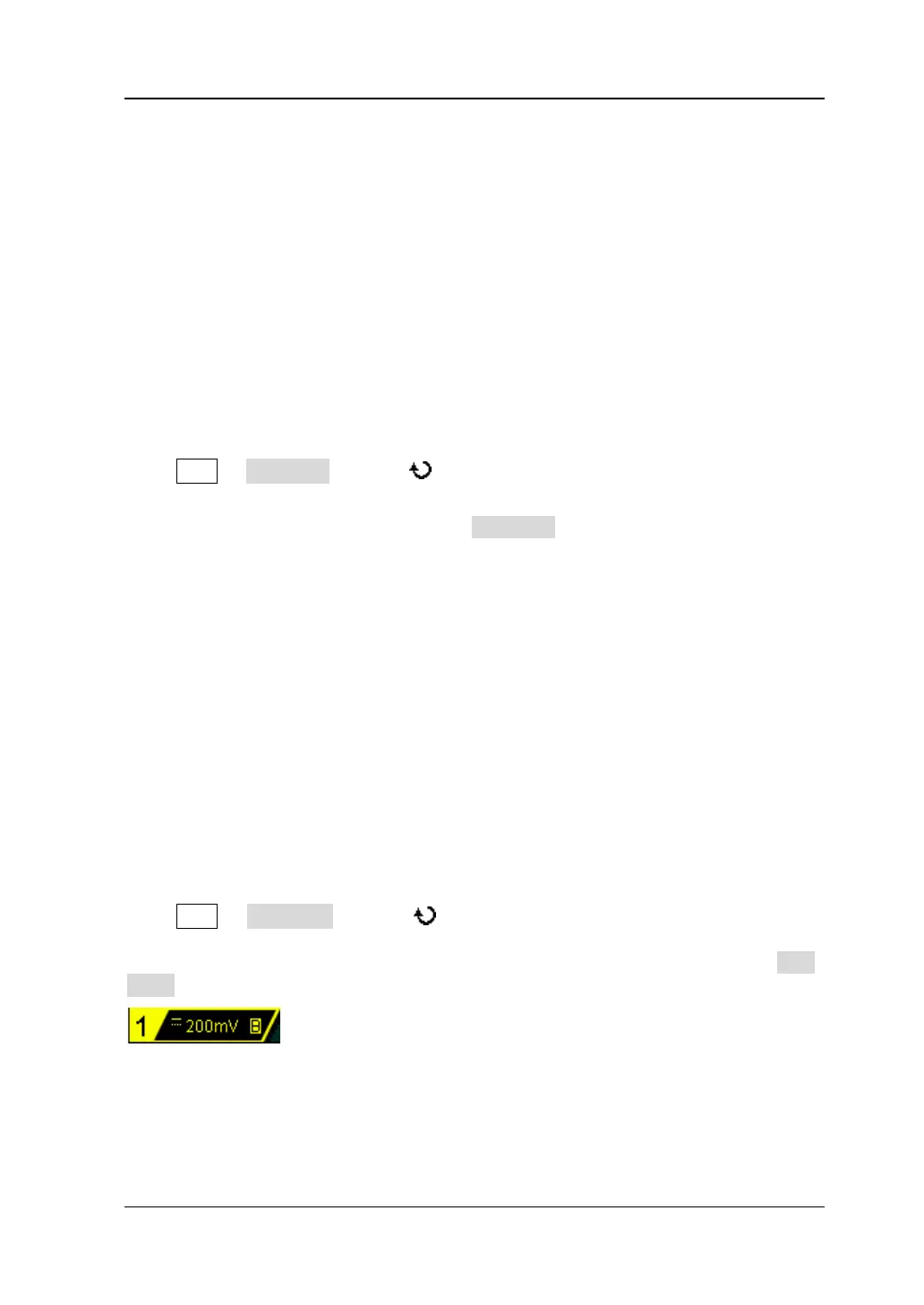
Press CH1 BW Limit and use to enable or disable bandwidth limit (the
default is OFF). When bandwidth limit (20 MHz) is enabled, the character “B” will be
displayed in the channel label at the bottom of the screen. You can also press BW
Limit continuously to switch between on and off of the bandwidth limit.
 Loading...