Rockwell Automation Publication 1766-UM001O-EN-P - September 2021 183
Appendix E Connect to Networks via RS-232/RS-485 Interface
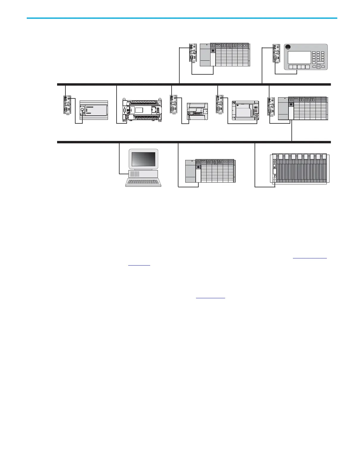
Figure 72 - MicroLogix 1400 Controller in a DH-485 Network
Example DH-485 Connections
The
following network diagrams provide examples of how to connect
MicroLogix controllers to the DH-485 network. You can connect a MicroLogix
1400 controller to your DH-485 network directly without using a RS-232 to
RS-485 converter and optical isolator, such as the Advanced Interface
Converter (AIC+), catalog number 1761-NET-AIC, as shown in Figure 73 on
page 184, because Channel 0 has isolation and RS-485 built-in.
However, you may need to use an AIC+ to connect Channel 2 of the MicroLogix
1400 controller to a DH-485 network. For more information on the AIC+, see
the Advanced Interface Converter and DeviceNet Interface Installation
Instructions, publication 1761-IN002.
A-B
PanelView
TERM
A
B
COM
SHLD
CHS GND
TX
TX PWR
TX
DC SOURCE
CABLE
EXTERNAL
TERM
A
B
COM
SHLD
CHS GND
TX
TX PWR
TX
DC SOURCE
CABLE
EXTERNAL
TERM
A
B
COM
SHLD
CHS GND
TX
TX PWR
TX
DC SOURCE
CABLE
EXTERNAL
TERM
A
B
COM
SHLD
CHS GND
TX
TX PWR
TX
DC SOURCE
CABLE
EXTERNAL
TERM
A
B
COM
SHLD
CHS GND
TX
TX PWR
TX
DC SOURCE
CABLE
EXTERNAL
TERM
A
B
COM
SHLD
CHS GND
TX
TX PWR
TX
DC SOURCE
CABLE
EXTERNAL
AIC+ AIC+ AIC+
AIC+
DH-485 Network
SLC 5/04 PanelView 550
MicroLogix 1500MicroLogix 1000 MicroLogix 1200 SLC 5/04
AIC+
AIC+
SLC 5/04 PLC-5
DH+ Network
Personal Computer
MicroLogix 1400
 Loading...


