Rockwell Automation Publication 1766-UM001O-EN-P - September 2021 61
Chapter 4 Communication Connections
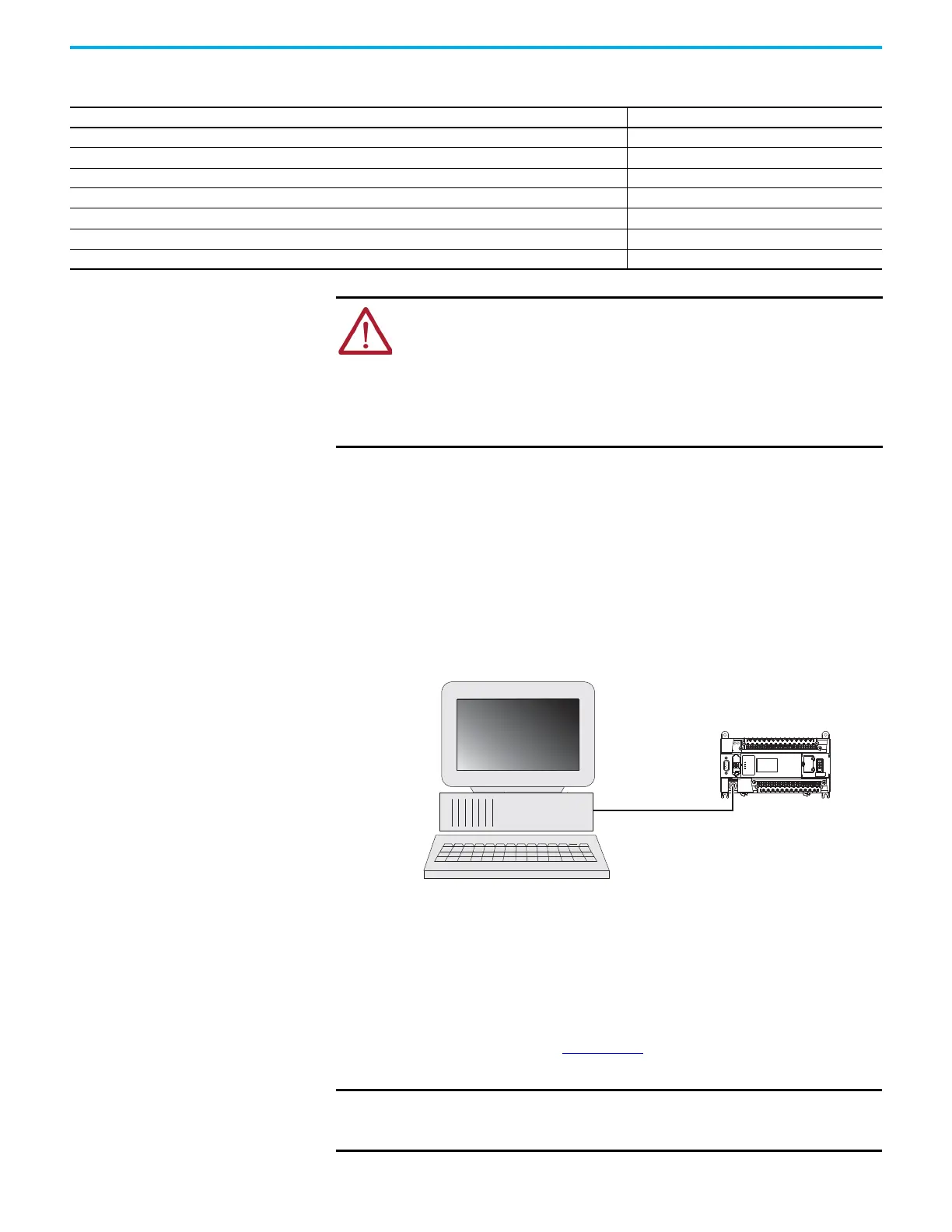
Make a DF1 Point-to-Point Connection
You can connect the MicroLogix 1400 programmable controller to your
personal computer using a serial cable (1761-CBL-PM02) from your personal
computer’s serial port to the controller’s Channel 0. The recommended
protocol for this configuration is DF1 Full-Duplex.
You can connect a MicroLogix 1400 controller to your personal computer
directly without using an external optical isolator, such as Advanced Interface
Converter (AIC+), catalog number 1761-NET-AIC, as shown in the illustration
below, because Channel 0 is isolated within the controller.
Modem
You can use modems to connect a personal computer to one MicroLogix 1400
controller (using DF1 Full-Duplex protocol), to multiple controllers (using DF1
Half-Duplex protocol), or Modbus RTU Slave protocol via Channel 0, as shown
in the following illustration. See Appendix E
for information on types of
modems you can use with the micro controllers.
Table 7 - Available Communication Cables
Communication Cables Length
1761-CBL-AM00 Series C or later cables are required for Class I Div 2 applications. 45 cm (17.7 in.)
1761-CBL-AP00 Series C or later cables are required for Class I Div 2 applications. 45 cm (17.7 in.)
1761-CBL-PM02 Series C or later cables are required for Class I Div 2 applications. 2 m (6.5 ft)
1761-CBL-HM02 Series C or later cables are required for Class I Div 2 applications. 2 m (6.5 ft)
2707-NC9 Series C or later cables are required for Class I Div 2 applications. 15 m (49.2 ft)
1763-NC01 Series A or later 30 cm (11.8 in.)
1747-CP3 Series A or later 3 m (9.8 ft)
ATTENTION: UNSUPPORTED CONNECTION
Do not connect a MicroLogix 1400 controller to another MicroLogix family
controller such as MicroLogix 1200 or to the 1747-DPS1 Network port using a
1761-CBL-AM00 (8-pin mini-DIN to 8-pin mini-DIN) cable or equivalent.
This type of connection will cause damage to the RS-232/RS-485 communication
port (Channel 0) of the MicroLogix 1400 and/or the controller itself.
Communication pins used for RS-485 communications are alternately used for
24V power on the other MicroLogix controllers and the 1747-DPS1 network port.
IMPORTANT Do not attempt to use DH-485 protocol through modems under any
circumstance. The communication timing using DH-485 protocol is not
supported by modem communications.
MicroLogix 1400 channel 0
Personal
computer
1761-CBL-AP00 or
1761-CBL-PM02
1)
(1) Series C or later cables are required for Class I Div 2 applications.
 Loading...


