Rockwell Automation Publication 1766-UM001O-EN-P - September 2021 293
Appendix H
System Loading and Heat Dissipation
System Loading
Calculations
The MicroLogix 1400 controller is designed to support up to any seven 1762
expansion I/O modules.
When you connect MicroLogix accessories and expansion I/O, an electrical
load is placed on the controller power supply. This section shows how to
calculate the load of your control system.
The following example is provided to illustrate system loading calculation.
The system calculation procedure accounts for the amount of 5V DC and 24V
DC current consumed by controller, expansion I/O, and user-supplied
equipment. Use the System Loading Worksheet
on page 294 to calculate your
controller configuration.
System Loading Example Calculations
Current Loading
Topic Page
System Loading Calculations 293
System Loading Worksheet 294
Calculating Heat Dissipation 296
A maximum of seven 1762 I/O modules, in any combination, can be connected to a
MicroLogix 1400 controller. You can use this appendix to determine the power supply
load and heat dissipation for
your system.
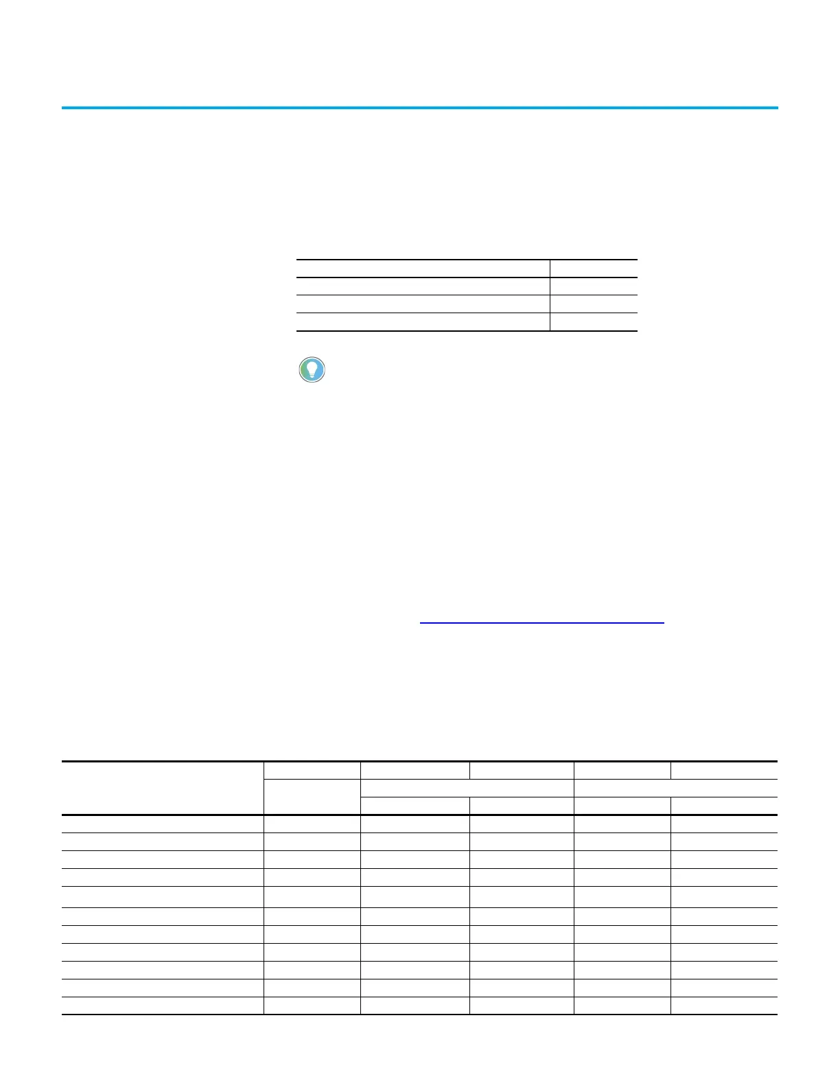
Table 46 - Calculating the Current for Expansion I/O
Catalog Number
(1)
n A B n x A n x B
Number of Modules
Device Current Requirements (max) Calculated Current
at 5V DC (mA) at 24V DC (mA) at 5V DC (mA) at 24V DC (mA)
1762-IA8 2 50 0 100 0
1762-IF4 40 50
1762-IF2OF2 40 105
1762-IQ8 50 0
1762-IQ16
70
(2)
0
1762-IQ32T 170 0
1762-IR4 40 50
1762-IT4 40 50
1762-OA8 115 0
1762-OB8 115 0
1762-OB16 175 0
 Loading...


